
The Diagnostic Power of a 3-Way Dimmer Wiring Diagram
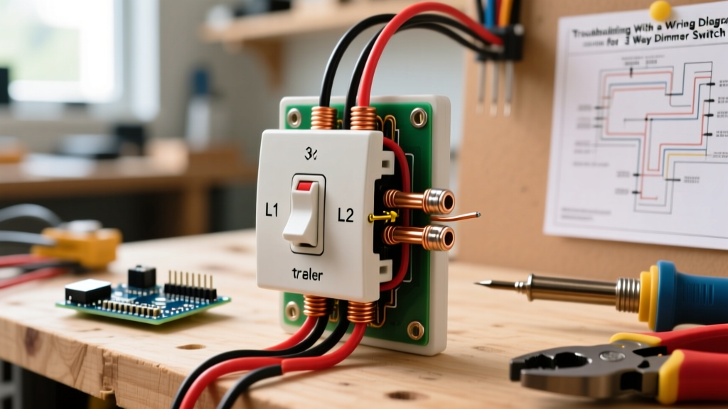
When a multi-location lighting circuit fails, most homeowners immediately suspect a burnt-out bulb or a tripped breaker. However, in modern electrical systems, the culprit is often a miswired or incompatible dimmer. As of 2026, the widespread adoption of high-efficacy LED fixtures and smart home ecosystems has made multi-location dimming more complex than ever. When you are staring at a wall box full of red, black, and blue wires, a standard wiring diagram for a 3 way dimmer switch transitions from a simple installation guide into your primary diagnostic map.
Unlike a standard single-pole switch that merely interrupts a single hot wire, a 3-way dimmer relies on a delicate balance of line voltage, load routing, and traveler communication. If your lights are flickering at low dimming levels, buzzing audibly, or only responding from one location, you must use the wiring diagram to isolate the fault. This guide will walk you through advanced troubleshooting protocols using the industry-standard Lutron Maestro LED+ (MACL-153MH, retailing around $38) and the Leviton Decora Universal (D6605, retailing around $32) as our diagnostic baseline.
Anatomy of the Circuit: Mapping the Terminals
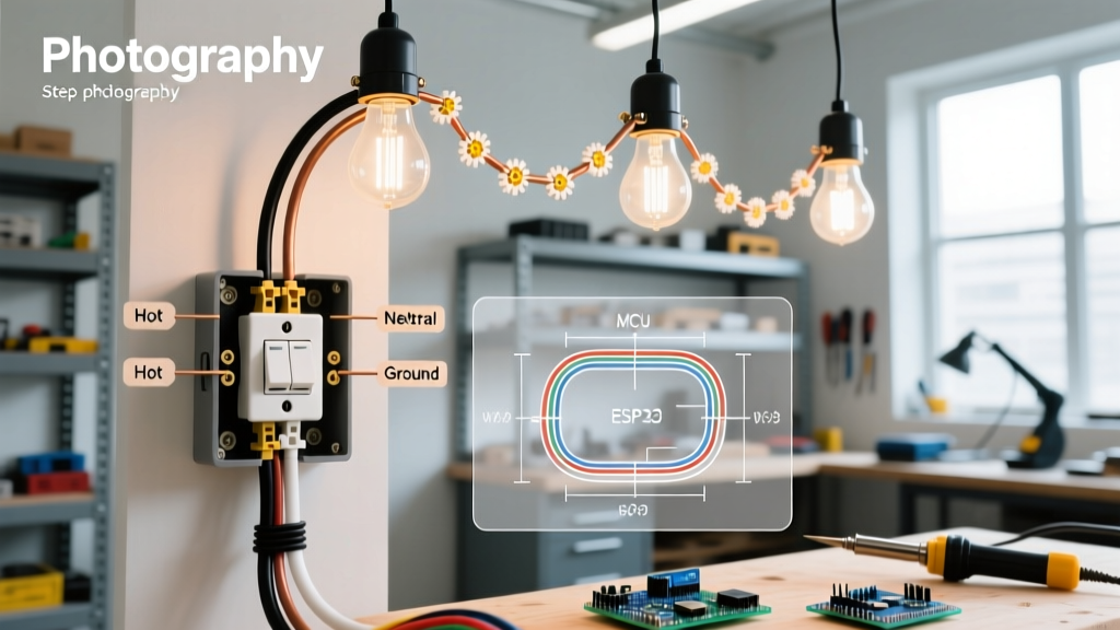
Before pulling out a multimeter, you must understand what the wiring diagram for a 3 way dimmer switch is actually telling you. A standard analog 3-way dimmer does not use a neutral wire (though smart 3-way dimmers do). It relies on four primary connections:
- Line (Hot): The continuous 120V AC power coming from the breaker panel. Usually black.
- Load: The switched hot wire traveling to the light fixture. Often red or black.
- Traveler 1 & Traveler 2: The communication wires that run between the two switch locations. In modern Romex (NM-B) 3-wire cable, these are typically red and black, or red and white (re-marked with black tape).
- Ground: Bare copper or green, essential for the dimmer's internal heat sink and EMI filtering.
Diagnostic Note: If you are installing a smart 3-way system like the Lutron Caseta (PD-5WS-DV), the wiring diagram will mandate a Neutral (White) connection to power the internal radio transceiver. Missing this neutral is the number one cause of smart 3-way switch failure.
Diagnostic Matrix: Symptom vs. Wiring Fault
Use this matrix to cross-reference your physical symptoms with the schematic logic of your wiring diagram.
| Observed Symptom | Probable Wiring Fault | Multimeter Test Required | Corrective Action |
|---|---|---|---|
| Lights flicker or drop out below 30% dimming | Incompatible LED driver or low-end trim misconfigured | N/A (Configuration issue) | Adjust low-end trim potentiometer or digital setting; verify LED is dimmable. |
| Switch works from Location A, but dead from Location B | Severed or miswired Traveler wire; Companion switch failure | Continuity test on Travelers (Power OFF) | Trace traveler wires with tone generator; replace companion switch if continuity is good. |
| Audible buzzing from the dimmer wall plate | Overloaded circuit or inductive load on a leading-edge TRIAC | AC Voltage (V~) and Clamp Meter Amp draw | Ensure total LED wattage is under 150W (Lutron limit); switch to ELV (trailing-edge) dimmer. |
| Breaker trips immediately upon reset | Line/Load reversal causing internal short, or pinched ground | Resistance/Short test between Hot and Ground | Re-verify Line vs. Load using non-contact voltage tester before connecting dimmer. |
Deep Dive: Troubleshooting the Top 3 Failure Modes
1. The "Location B" Dead Zone (Traveler Faults)
The most common reason a homeowner searches for a wiring diagram for a 3 way dimmer switch is that the lights only turn on from one side of the hallway. In a standard 3-way setup, the mechanical switch at Location B simply swaps which traveler wire is receiving voltage. However, in a 3-way dimmer setup (like the Lutron Maestro with an MA-R companion), the companion switch sends digital pulses over the traveler wire to tell the master dimmer to adjust the phase-cut waveform.
The Fix: Turn off the breaker. Disconnect the traveler wires at both the master and companion switches. Set your multimeter to the Continuity (beep) setting. Place one probe on Traveler 1 at Location A, and the other on Traveler 1 at Location B. If there is no beep, the wire is broken inside the wall or a wire nut has failed in a ceiling junction box. If continuity is perfect, the companion switch's internal logic board has failed and must be replaced.
2. LED Flickering and the TRIAC Waveform
Standard dimmers use a TRIAC to chop the AC sine wave, turning the power on and off 120 times per second (forward phase-cutting). Older incandescent bulbs smoothed this out via thermal inertia. Modern LEDs, however, react instantly to these micro-interruptions. If your wiring is perfectly matched to the diagram but the lights strobe at low levels, you are experiencing a waveform mismatch.
The Fix: Do not rewire the circuit. Instead, access the dimmer's low-end trim. On the Lutron MACL-153MH, press and hold the bottom rocker switch for 6 seconds until the LEDs flash, then use the up/down rockers to raise the minimum voltage until the flickering stops. According to the U.S. Department of Energy, ensuring your LED bulbs are specifically rated for "phase-cut dimming" is critical, as standard non-dimmable LED drivers will actively fight the dimmer's chopped waveform.
3. The Heat Sink and Audible Buzzing
Dimmers dissipate excess energy as heat. If you hear a loud hum, the internal inductor coil is vibrating due to harmonic distortion, usually caused by exceeding the dimmer's wattage rating. While a Lutron Maestro is rated for 600W of incandescent light, its LED rating is strictly capped at 150W (or roughly 15 standard 10W LED bulbs). Furthermore, if you removed the side fins (heat sink tabs) to fit the dimmer into a multi-gang box, you must derate the maximum wattage by 30%.
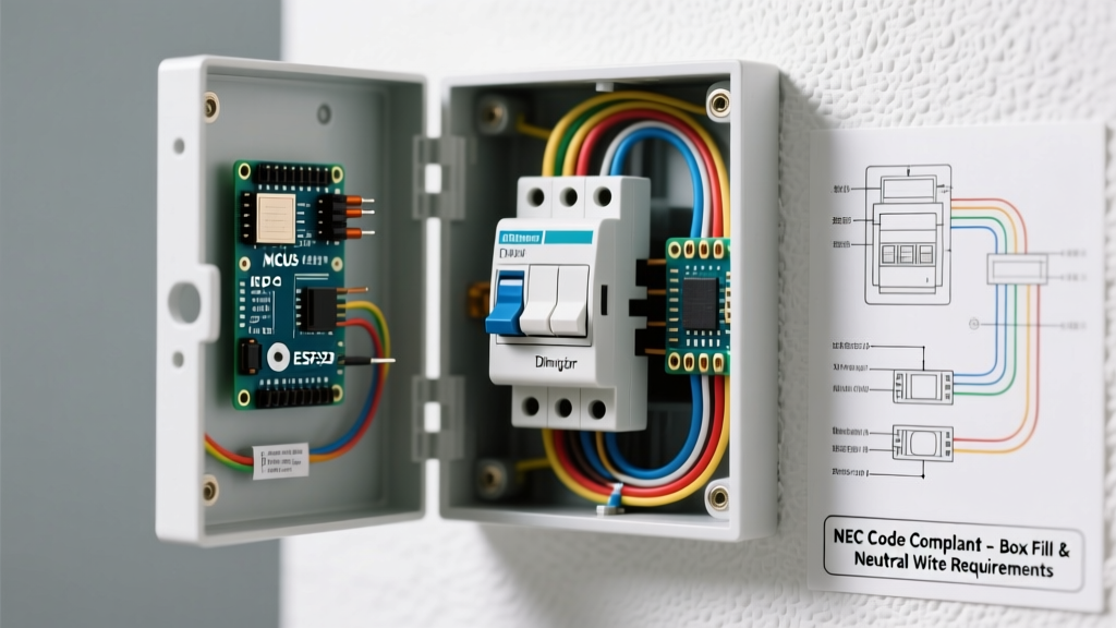
Safety & Code Compliance: According to the National Electrical Code (NEC) Article 404, switches must be installed in boxes that provide adequate volume for heat dissipation and wire bending space. Overcrowding a standard 18-cubic-inch single-gang box with a deep-body smart dimmer and four 12-AWG wires violates box-fill calculations and creates a severe fire hazard. Always upgrade to a 22-cubic-inch deep box when retrofitting 3-way smart dimmers.
Step-by-Step Multimeter Diagnostic Protocol
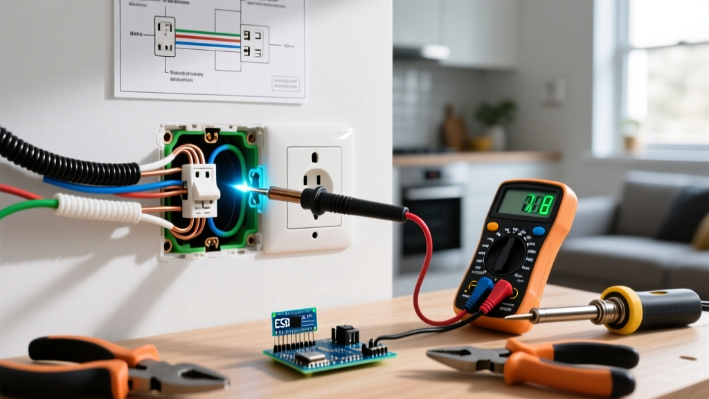
When the wiring diagram for a 3 way dimmer switch doesn't solve the issue visually, you must verify the electrical reality. Follow this exact sequence to prevent equipment damage and ensure personal safety, adhering to guidelines established by the Electrical Safety Foundation International (ESFI).
- Kill and Verify: Turn off the 15A or 20A breaker. Use a Non-Contact Voltage Tester (NCVT) on the wall plate screws and inside the box to confirm zero voltage. Never trust the switch position alone.
- Identify the True Line: If the wires are unmarked, separate all wires, turn the breaker back on briefly, and use the NCVT to find the single wire that is hot. This is your Line. Tag it with black electrical tape. Turn the breaker off again.
- Trace the Load: The Load wire goes to the fixture. If you are unsure which of the remaining wires is the Load, use a multimeter set to AC Voltage. With the breaker ON, measure between the known Line and the suspected Load while an assistant toggles a temporary standard switch. (Alternatively, use a continuity tester with the power OFF between the suspected Load and the fixture's black wire in the ceiling).
- Verify Traveler Integrity: With power OFF, disconnect the travelers. Measure resistance between the two traveler wires at Location A. If you read infinite resistance (OL), the wires are intact and isolated. If you read near-zero ohms, the travelers are shorted together somewhere in the wall, which will instantly destroy a smart companion switch upon power-up.
When to Abandon Analog for Smart 3-Way Systems
If you are repeatedly troubleshooting traveler wire faults in an older home where the original 3-wire Romex is degraded or improperly spliced in inaccessible attic junctions, the physical wiring diagram for a 3 way dimmer switch becomes a liability. In 2026, the most reliable diagnostic workaround for faulty traveler wires is to bypass them entirely using wireless smart switches.
By installing a master smart dimmer (like the Lutron Caseta PD-6WCL) at the Line/Load location, and capping off the faulty traveler wires, you can install a battery-powered Pico remote (PJ2-3BRL) at Location B. This completely eliminates the physical traveler wires from the equation, solving 90% of multi-location diagnostic nightmares without requiring a single new wire to be pulled through the drywall.
Final Diagnostic Takeaways
Troubleshooting a multi-location lighting circuit requires moving beyond simple on/off logic. By keeping the wiring diagram for a 3 way dimmer switch in front of you, methodically testing traveler continuity, and respecting the strict LED wattage limits of modern TRIAC dimmers, you can isolate and resolve almost any flickering, buzzing, or dead-switch fault. Always prioritize box-fill compliance and verify your line/load orientation before securing the yoke to the wall.