
The Switch Loop Dilemma: Why Your Outlet Isn't Working
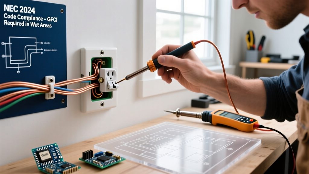
Adding an electrical outlet from light switch boxes is a common DIY attempt to gain a convenient plug for a phone charger, a smart home hub, or a vacuum cleaner. However, homeowners frequently encounter a frustrating scenario: the new receptacle is completely dead, it only powers on when the overhead light is switched on, or it immediately trips the circuit breaker.
This almost always traces back to a wiring configuration known as a switch loop. In older homes (and even some newer ones depending on local code adoption timelines), the cable running from the ceiling fixture down to the wall switch contains only a constant hot wire and a switched return leg. Crucially, there is no neutral wire at the switch box. Without a neutral, a standard 120V duplex receptacle cannot complete its circuit. Attempting to force an outlet onto this circuit without proper troubleshooting leads to code violations, equipment damage, and severe shock hazards.
⚠️ CRITICAL SAFETY WARNING: Before removing any faceplate or testing wires, turn off the circuit breaker and verify zero voltage using a Non-Contact Voltage Tester (NCVT). According to OSHA electrical safety guidelines, treating every conductor as energized until proven otherwise is mandatory to prevent arc flash and fatal electrocution.
Diagnostic Matrix: Identifying Your Specific Failure Mode
To properly troubleshoot an electrical outlet from light switch wiring, you must first categorize the exact symptom you are experiencing. Use a digital multimeter (such as the Klein Tools MM400 or Fluke 117) set to AC Voltage (V~) to perform the following diagnostic checks.
| Symptom | Probable Root Cause | Multimeter Test (Probe Points) | Expected Reading |
|---|---|---|---|
| Outlet only works when light switch is ON | Receptacle is wired to the 'Switched Leg' instead of the constant 'Line' hot. | Black (Hot) to Bare Copper (Ground) | 0V (Switch OFF) / ~120V (Switch ON) |
| Outlet is completely dead (Light works fine) | Missing neutral wire; outlet wired to ground instead of neutral (Bootleg neutral). | Black (Hot) to White (Supposed Neutral) | 0V or phantom voltage (~10-40V) |
| Breaker trips immediately upon resetting | Direct short circuit; neutral and ground bonded at the receptacle, or hot wired to ground. | Check continuity with power OFF. Hot to Ground. | 0.0 Ohms (Dead Short) |
| GFCI breaker trips, standard breaker holds | Current leaking to ground; often caused by using the bare ground wire as a current-carrying neutral. | Measure current on ground wire with clamp meter. | >5mA leakage detected |
Deep Dive: The Missing Neutral & NEC Code Violations
If your multimeter confirms you have ~120V between the black (hot) wire and the bare copper (ground) wire, but 0V between the black wire and the white wire, you have confirmed a missing neutral.
In a standard switch loop using 14/2 or 12/2 NM-B (Romex) cable, the white wire is re-identified with black tape and serves as the constant hot feed from the ceiling fixture. The black wire serves as the switched hot returning to the fixture. Because neither of these wires returns to the neutral bus bar in your main panel, you cannot tap into them to power a receptacle.
The Lethal "Bootleg Neutral" Hack
A dangerous and surprisingly common DIY hack involves wiring the silver (neutral) terminal of the new receptacle to the bare copper ground wire. Because the ground wire eventually connects to the neutral bus bar at the main panel, the outlet will appear to work and power a device. This is a severe violation of NEC Article 250.148 and is potentially lethal.
If a fault occurs, or if the ground connection becomes loose anywhere in the circuit, the bare copper wires and the metal faceplate screws of your outlet will become energized at 120V. Furthermore, this hack will cause any upstream GFCI protection to trip immediately, as the current returning on the ground wire creates an imbalance that the GFCI sensor will detect as a ground fault.
Box Fill Calculations: Will the Outlet Even Fit?
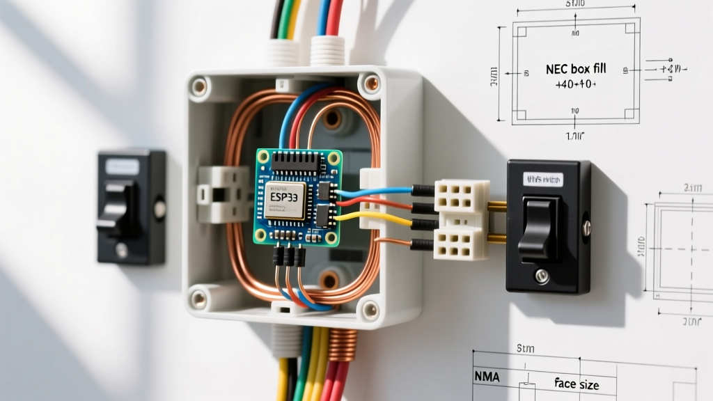
Even if you successfully locate a constant hot and a neutral at the switch box, you must perform a box fill calculation per NEC Article 314.16(B). Many older homes use shallow 14-cubic-inch single-gang switch boxes. Adding a duplex receptacle to a box already crowded with switch wiring often violates code and creates a fire hazard due to crushed conductors and excessive heat buildup.
Calculating Box Fill for a Standard 15-Amp Circuit (14 AWG Wire)
- Each current-carrying conductor: 2.0 cubic inches (Hot, Neutral, Switched Leg)
- All grounding conductors combined: 2.0 cubic inches (1 allowance total)
- Internal cable clamps: 2.0 cubic inches (1 allowance total)
- Switch device: 4.0 cubic inches (2 allowances)
- Receptacle device: 4.0 cubic inches (2 allowances)
Total Required Volume: If you have 1 feed cable (hot/neutral/ground), 1 switch loop cable (hot/switched/ground), 2 devices, and 1 clamp, your calculation is: 4 wires (8 cu in) + 1 ground (2 cu in) + 1 clamp (2 cu in) + 2 devices (8 cu in) = 20 cubic inches minimum. If your existing box is only 14 or 18 cubic inches, you must upgrade to a deep 22.5 cu in old-work box or add an adjacent junction box.
Code-Compliant Solutions for Adding an Outlet
Once you have diagnosed that your existing switch loop lacks a neutral and the box is too small, you must choose a code-compliant path forward. As of 2026, local inspectors are strictly enforcing the 2023 NEC updates regarding neutral availability and box fill.
Solution A: Pull a New 14/3 or 12/3 Cable from the Fixture
If the ceiling fixture is accessible via an unfinished attic, the most elegant solution is to replace the existing 2-conductor switch loop cable with a 3-conductor cable (14/3 for 15A circuits, 12/3 for 20A circuits).
- Process: Run the new cable from the ceiling junction box down to the switch box. The white wire becomes the dedicated neutral, the black becomes the constant hot, the red becomes the switched leg, and the bare copper remains the ground.
- Cost: ~$0.90 per foot for 14/3 NM-B cable, plus ~$1.50 for a Leviton 15A commercial-grade receptacle.
- Time: 2 to 4 hours, depending on attic accessibility and drywall fishing.
Solution B: Tap an Adjacent Outlet Circuit
If the ceiling is sealed or inaccessible, abandon the idea of powering the electrical outlet from light switch wiring entirely. Instead, locate a nearby wall receptacle on the opposite side of the stud bay or in an adjacent room.
- Process: Cut a new hole, install an old-work bracket, and run a new 14/2 or 12/2 cable from the adjacent outlet's line and neutral terminals to your new switch-box outlet. Ensure you are not mixing 15A and 20A circuits, and verify the existing circuit has the ampacity to handle the additional load.
- Code Note: You must ensure the new receptacle is properly grounded and that the originating circuit is not a dedicated appliance circuit (e.g., kitchen countertop or bathroom receptacle circuits per NEC 210.11).
Final Verification and Testing
After executing your chosen repair, do not simply plug in a device and hope for the best. Follow the CPSC home electrical safety testing protocols:
- Restore power at the breaker panel.
- Use a standard 3-light receptacle tester (e.g., Gardner Bender GRT-501) to verify correct wiring (two amber lights indicate correct wiring).
- Use your multimeter to verify ~120V between Hot and Neutral, and ~120V between Hot and Ground.
- Verify 0V between Neutral and Ground. Any reading above 1-2V here indicates a loose neutral connection upstream, which requires immediate attention.
Troubleshooting an electrical outlet from light switch configurations requires patience, a solid understanding of circuit topology, and strict adherence to the National Electrical Code. By diagnosing the missing neutral and avoiding dangerous bootleg hacks, you ensure your home's electrical system remains safe, functional, and up to modern standards.