
Decoding the 7-Pin Wiring Diagram for a Trailer Plug: An Inspection Guide
When a trailer lighting system fails, most DIYers immediately blame the bulbs or the tow vehicle's fuse box. However, industry diagnostics reveal that over 70% of trailer electrical faults originate at the connector interface. Understanding and physically testing a wiring diagram for a trailer plug requires more than just a visual continuity check; it demands load testing, voltage drop analysis, and an understanding of modern pulse-width modulation (PWM) interference.
This inspection guide moves beyond basic pinout charts. We will walk through the exact diagnostic protocols used by master technicians to verify 7-way RV blade connectors against the SAE J286 standard, ensuring your rig is safe, legal, and fully functional before hitting the highway.
The SAE J286 Standard: 7-Way RV Blade Pinout Matrix
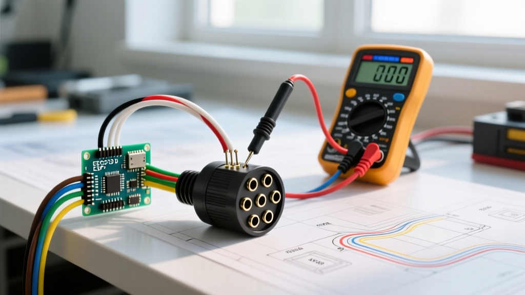
Before connecting a multimeter, you must map the physical plug to its intended circuit. The 7-way RV blade (commonly found on models like the Curt 58150 or Hopkins 40975) follows the SAE J286 standard. According to SAE International, this configuration separates high-draw circuits from sensitive signal circuits to prevent voltage sag and cross-talk.
| Pin Position | Wire Color | Circuit Function | Minimum Wire Gauge | Expected Voltage (Engine On) |
|---|---|---|---|---|
| Center (Pin 1) | White | Ground Return | 10 AWG | 0.0V (Relative to Chassis) |
| Pin 2 | Blue | Electric Brakes | 10 AWG | 0.0V - 12.0V (PWM Signal) |
| Pin 3 | Green | Tail / Running Lights | 12 AWG | 13.2V - 14.4V |
| Pin 4 | Black | 12V Auxiliary / Battery Charge | 10 AWG | 13.2V - 14.4V |
| Pin 5 | Red | Left Turn / Stop | 12 AWG | 0.0V / 13.2V - 14.4V |
| Pin 6 | Brown | Right Turn / Stop | 12 AWG | 0.0V / 13.2V - 14.4V |
| Pin 7 | Yellow | Reverse Lights / Aux | 12 AWG | 13.2V - 14.4V (In Reverse) |
Essential Diagnostic Equipment
Do not rely on cheap incandescent test lights for modern tow vehicles. Late-model trucks utilize multiplexed wiring and solid-state relays that can be damaged by the current draw of a standard test light. Assemble the following tools before beginning your inspection:
- Digital Multimeter (DMM): A True-RMS meter like the Fluke 117 is required to accurately read the pulsed DC signals from modern brake controllers.
- LED Circuit Tester: The Hopkins 20115 draws minimal current and safely simulates a trailer load without triggering the tow vehicle's bulb-out warning modules.
- Dielectric Grease: Permatex 22058 to seal the connector post-testing.
- Wire Piercing Probes: For testing upstream of the plug without stripping insulation.
Step-by-Step Inspection and Testing Protocol
Phase 1: The Ground Circuit Load Test (The 0.2V Rule)
The white ground wire is the single most common point of failure. A poor ground causes backfeed, resulting in running lights illuminating when the brakes are pressed. According to diagnostic standards outlined by Fluke Corporation, voltage drop testing is the only reliable way to verify ground integrity under load.
- Turn on the tow vehicle's running lights (Pin 3).
- Set your DMM to DC Volts.
- Place the red probe on the tow vehicle's bare chassis ground (not the battery negative).
- Place the black probe directly on the trailer plug's white ground pin.
- Pass Criteria: The reading must be 0.2V or less. A reading of 0.5V or higher indicates severe corrosion or an undersized ground wire. The ground must be upgraded to 10 AWG and bolted directly to the trailer frame, bypassing any rust-prone hinges or couplers.
Phase 2: Signal and Lighting Verification
With the ground verified, test the lighting circuits. Modern trucks equipped with NHTSA-regulated lighting modules will cut power if they detect a short or an open circuit.
- Turn Signals (Pins 5 & 6): Activate the hazard lights. Probe Pins 5 and 6. You should see a pulsing 12V-14V reading. If your DMM reads a steady 6V-8V, the truck's flasher module is likely detecting an LED trailer load mismatch and is operating in 'limp mode'.
- Auxiliary Power (Pin 4): This circuit is often tied to a relay in the engine bay. Verify it reads 0V with the key off, and jumps to >13.2V only when the ignition is in the 'Run' or 'Accessory' position. Continuous 12V with the key off will drain your truck's starter battery overnight.
Phase 3: Electric Brake PWM Signal Analysis
Pin 2 (Blue) does not supply a steady 12V. Modern proportional brake controllers (like the Tekonsha P3 or Redarc Tow-Pro Elite) output a Pulse-Width Modulated (PWM) signal. A standard DMM might display erratic readings between 4V and 9V. To properly test this pin, you must use a DMM with a 'Min/Max' or 'Duty Cycle' function, or an oscilloscope. When the manual override slider is pulled to 100%, the True-RMS voltage should stabilize near the vehicle's alternator output (approx. 13.8V).
Advanced Edge Cases & Failure Modes
Expert Insight: Never use standard incandescent flasher relays on a truck towing an all-LED trailer. The low current draw of LEDs (often under 0.5A total for the entire trailer) will cause hyper-flashing or cause the truck's Body Control Module (BCM) to throw a 'Trailer Wiring Fault' code on the dashboard.
Edge Case 1: LED Hyperflashing and BCM Faults
If your wiring diagram for a trailer plug shows correct continuity, but the truck dashboard displays a lighting fault, the issue is current draw. The truck's BCM expects a 2.5A load from incandescent bulbs. The Fix: Install a Curt 57003 LED load resistor module inline on the left and right turn circuits (Pins 5 and 6) at the trailer junction box, not at the plug itself, to dissipate heat safely.
Edge Case 2: The 'Backfeed' Ghost Voltage
Sometimes, testing Pin 3 (Running Lights) will show 4V-6V even when the truck's lights are turned off. This 'ghost voltage' is caused by internal corrosion inside the 7-way plug creating a high-resistance bridge between the 12V Auxiliary pin (Pin 4) and the lighting pins. Moisture acts as a semiconductor. The Fix: Disassemble the plug housing, clean the brass contacts with contact cleaner, apply Permatex dielectric grease, and re-crimp. If the plug is molded, replace the entire pigtail.
Expert Troubleshooting Matrix
Use this diagnostic matrix to quickly isolate faults when your physical inspection yields ambiguous results.
| Observed Symptom | DMM Reading at Plug | Probable Root Cause | Corrective Action |
|---|---|---|---|
| Brakes lock up when headlights are turned on | Pin 2 reads 12V when Pin 3 is active | Short between Green (Tail) and Blue (Brake) wires | Inspect trailer tongue wiring for pinch points; separate and re-tape. |
| Left turn signal flashes rapidly on dash | Pin 5 reads steady 7.5V | BCM detects low current (LED mismatch) | Install 6-ohm load resistor on left turn circuit at trailer junction. |
| Trailer battery drains while parked | Pin 4 reads 12.4V with key OFF | Faulty isolation relay in tow vehicle fuse box | Replace OEM trailer battery charge relay; verify ignition-switched trigger. |
| All trailer lights dim when brakes are applied | System voltage drops to 10.5V under load | Undersized ground wire or corroded frame bond | Upgrade ground to 10 AWG; sand frame to bare metal for ground ring terminal. |
Final Sealing and Maintenance
Once all pins pass the voltage and load tests, the final step in the inspection protocol is environmental sealing. Spray the male and female contacts with an electrical contact cleaner (like WD-40 Specialist Contact Cleaner) to remove any invisible oxidation layer. Once dry, pack the interior of the female plug with dielectric grease. This excludes moisture and prevents the galvanic corrosion that plagues 7-way connectors in winter and coastal environments. By treating the wiring diagram for a trailer plug as a living, testable circuit rather than just a static map, you ensure reliable, safe towing for years to come.