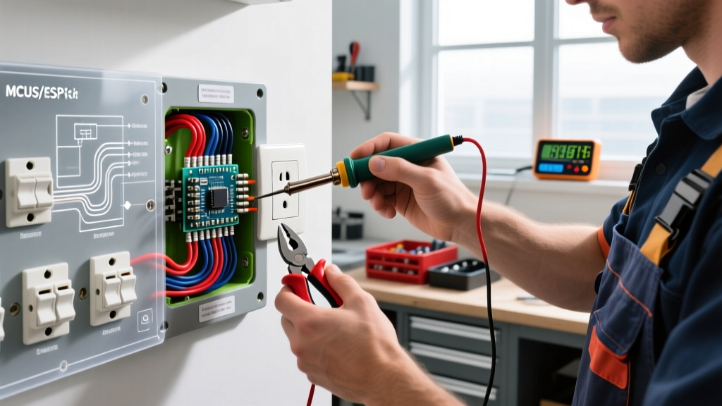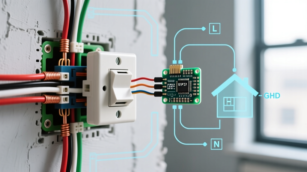

Why Electrical Outlet Dimensions Matter in Field Inspections
When conducting rough-in or final electrical inspections, verifying the physical dimensions of outlets, junction boxes, and wall clearances is just as critical as testing voltage and polarity. The electrical outlet dimensions standard is not a single arbitrary number; it is a complex matrix governed by NEMA (National Electrical Manufacturers Association) for device fitment, and the National Electrical Code (NEC) for box volume and spacing. Ignoring these dimensional standards leads to overcrowded junction boxes, overheating smart devices, and failed ADA compliance checks.
This inspection and testing guide breaks down the exact dimensional standards, box fill calculations, and physical testing protocols required to ensure your switch and outlet installations meet 2026 code requirements and function safely under load.
The NEMA WD-6 Standard: Device Face & Strap Dimensions
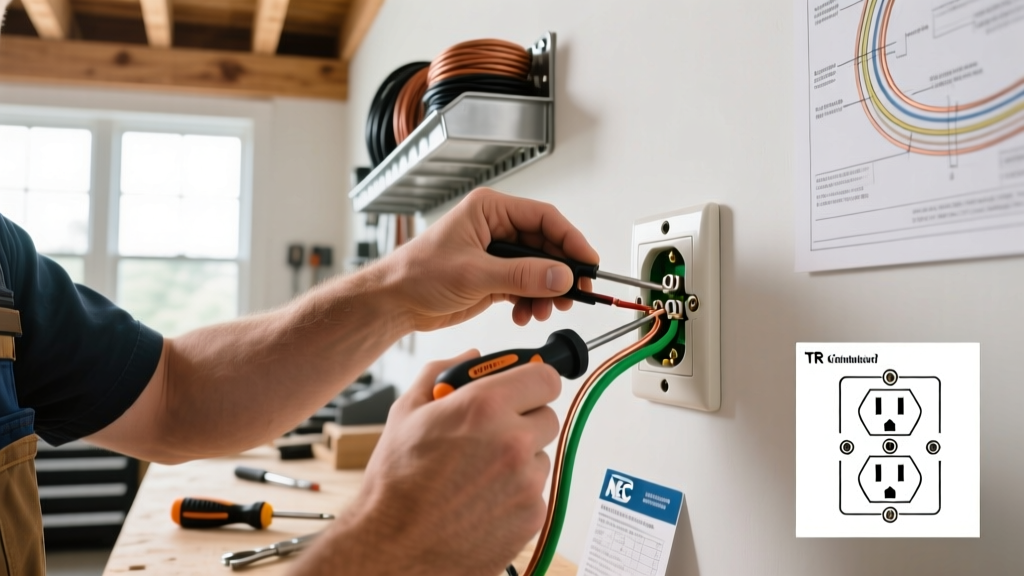
Inspectors must verify that the installed devices match the cover plates and junction boxes. The foundational standard for these physical dimensions in North America is NEMA WD-6 (Wiring Devices - Dimensional Requirements). Understanding the difference between standard duplex receptacles and Decora-style devices (used for GFCIs, AFCIs, and smart switches) is vital for identifying improper cover plate adaptations.
Standard Device Dimension Matrix
| Device Type | Strap (Yoke) Dimensions | Device Face Dimensions | Required Cover Plate Opening | Common Applications |
|---|---|---|---|---|
| Standard Duplex (NEMA 5-15R) | 3.28" x 1.31" | 2.62" x 1.31" (approx) | 1.312" x 2.625" (Twin) | Standard 15A/20A receptacles, toggle switches |
| Decora / Rocker Style | 4.19" x 1.31" | 2.62" x 1.31" (Rocker) | 1.312" x 2.625" (Single) | GFCI, AFCI, Dimmers, Smart Switches |
| Single Gang Cover Plate | N/A | N/A | 4.50" x 2.75" (Overall) | Fits all standard single-gang devices |
Inspector Note: A common field failure occurs when electricians install Decora-style GFCI receptacles in shallow boxes, then attempt to use standard duplex cover plates with modified cutouts. This violates fire containment standards and leaves exposed gaps that fail final inspection.
NEC Article 314: Junction Box Depth and Volume Requirements
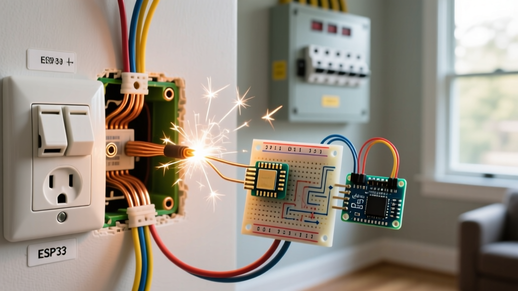
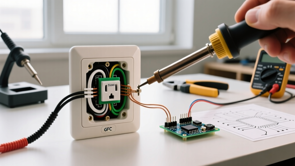
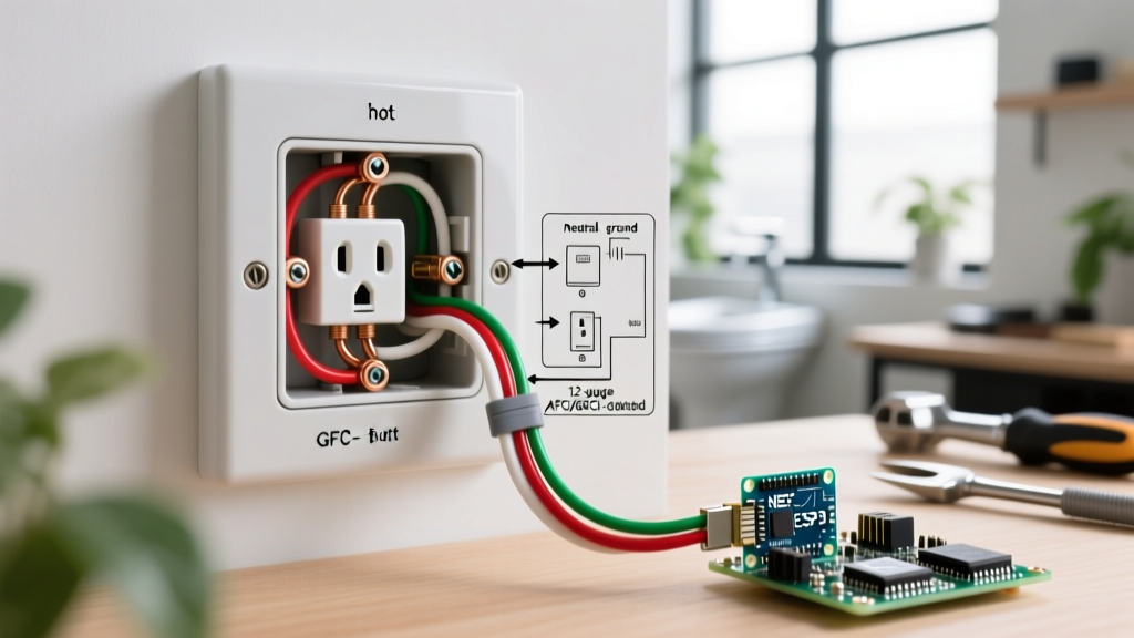
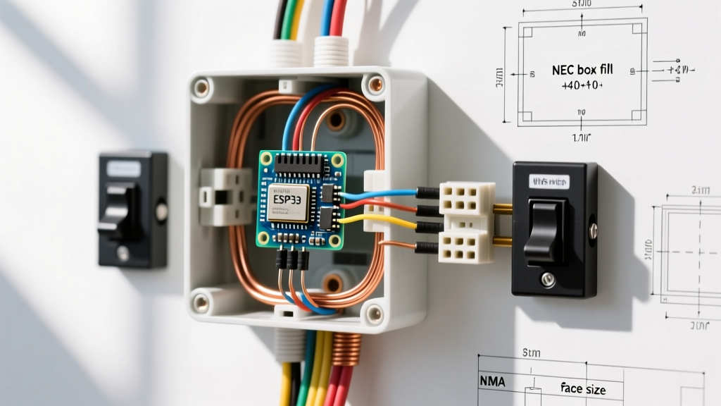
The most frequent dimensional violation cited during rough-in inspections relates to junction box volume. Modern electrical devices—particularly smart switches with Wi-Fi radios and GFCI receptacles with complex internal PCBs—are significantly deeper than legacy devices. The NEC strictly regulates box fill to prevent wire insulation damage and heat buildup.
Minimum Box Depth Guidelines for Modern Devices
- Standard Toggle/Duplex Receptacles: Minimum 1.5-inch depth (approx. 14 to 18 cubic inches).
- GFCI / AFCI Receptacles: Minimum 2.25-inch depth (minimum 22.5 cubic inches recommended).
- Smart Switches / Dimmers (e.g., Lutron Caseta, Leviton Decora Smart): Minimum 2.5-inch to 3.5-inch depth (22.5 to 30+ cubic inches) to accommodate the deep chassis and multiple wire nuts.
Calculating Box Fill (NEC 314.16(B))
During an inspection, if a box appears overfilled, you must calculate the exact volume. According to the National Electrical Code (NEC) Article 314.16, each conductor, device, and clamp consumes a specific volume allowance based on the largest wire gauge in the box.
| Wire Gauge (AWG) | Volume Allowance per Conductor | Device Allowance (Internal Clamps/Yoke) |
|---|---|---|
| 14 AWG | 2.0 cubic inches | 2 x 2.0 = 4.0 cubic inches |
| 12 AWG | 2.25 cubic inches | 2 x 2.25 = 4.5 cubic inches |
| 10 AWG | 2.5 cubic inches | 2 x 2.5 = 5.0 cubic inches |
Field Testing Tip: To quickly test for box fill violations without doing complex math on-site, count the number of 12 AWG wires entering a standard 18-cubic-inch single-gang box. If there are more than 4 current-carrying conductors plus a device (which counts as two), the box is legally overfilled and must be replaced with a 22.5 cu in deep box.
Spacing, Clearance, and ADA Height Standards
Inspection of outlet dimensions extends beyond the box itself to the spatial arrangement on the wall. NEC 210.52 dictates wall spacing, while the Americans with Disabilities Act (ADA) dictates mounting heights for commercial and accessible residential builds.
NEC 210.52 Wall Spacing Rules
- The 6/12 Rule: No point along a continuous wall line can be more than 6 feet from an outlet. Therefore, outlets must be spaced no more than 12 feet apart.
- Wall Width Threshold: Any wall space 24 inches or wider requires a dedicated receptacle.
- Countertop Spacing: Receptacles must be installed so that no point along the countertop wall line is more than 24 inches from an outlet (maximum 48 inches apart).
ADA Mounting Height Requirements
For commercial inspections or ADA-compliant residential projects, outlet and switch heights are strictly regulated to ensure wheelchair accessibility. The 2010 ADA Standards for Accessible Design (which remain the benchmark for physical reach ranges) mandate the following:
- Maximum Forward Reach: 48 inches from the finished floor to the center of the outlet/switch box.
- Minimum Forward Reach: 15 inches from the finished floor.
- Obstructed Reach: If reaching over an obstruction (like a counter), the maximum height drops to 44 inches if the depth of the obstruction is between 20 and 25 inches.
Standard Builder Grade: In non-ADA residential construction, the standard dimension from the finished floor to the bottom of the outlet box is typically 16 inches, while light switch boxes are set at 48 inches to the bottom of the box.
The Inspector’s Physical Fitment Testing Checklist
When performing a final inspection, visual checks are not enough. Use this step-by-step physical testing protocol to verify dimensional compliance and device integrity.
- The Flush-Mount Test: Place a 6-inch metal level across the face of the installed cover plate. The plate should sit perfectly flush with the drywall. If the plate bows outward, the device strap is bottoming out against the wires inside a shallow box—a major fire hazard.
- The Plaster Ear Check: On old-work (remodel) boxes, ensure the plaster ears are seated flat against the drywall surface. If the box is recessed more than 1/4-inch into a combustible wall surface (like wood paneling), NEC 314.20 requires a box extender ring to bridge the gap.
- The Strap Screw Tension Test: Tighten the 6-32 mounting screws using a hand screwdriver. If you encounter extreme resistance before the device seats, STOP. Forcing the screws can crack the polycarbonate face of a GFCI or damage the internal PCB of a smart switch.
- Mud Ring Verification (Metal Studs): For commercial builds using metal studs, verify that the adjustable mud rings are set exactly flush with the finished wall. A recessed mud ring causes the device yoke to flex when a plug is inserted, eventually loosening the terminal screws.
Troubleshooting Dimension-Related Failures
When an installation fails the dimensional inspection, electricians must deploy specific remediation strategies. Below are common field failures and their code-compliant solutions.
Problem: Smart Switch Protruding from Wall
Cause: The installer used a standard 14 cu in shallow nail-on box (1.5" depth) for a smart switch with a 2.2" deep chassis.
Solution: Cut out the drywall and install a 22.5 cu in "deep" old-work box (minimum 2.5" depth). Alternatively, use a surface-mount wire mold extension if drywall repair is not feasible, though this is aesthetically undesirable.
Problem: Cracked Drywall Around Cover Plate
Cause: The junction box was installed proud (sticking out) of the drywall by more than 1/8-inch. When the cover plate screws were tightened, the drywall paper and gypsum core fractured.
Solution: Loosen the box mounting nails/screws and tap the box back flush using a block of wood and a hammer. If the box is a nail-on type that cannot be moved, use a drywall rasp to carefully bevel the inside edge of the drywall cutout, allowing the cover plate to seat without crushing the gypsum.
Problem: GFCI Tripping Due to Heat Buildup
Cause: Overfilled 18 cu in box with 12 AWG wire. The sheer mass of copper and wire nuts is pressing against the back of the GFCI's internal circuit board, trapping heat and causing nuisance tripping under continuous load.
Solution: Upgrade to a 22.5 or 30 cubic inch extra-deep box. Use WAGO 221 lever nuts instead of bulky twist-on wire nuts to save up to 30% of the internal box volume, relieving physical pressure on the device.
Conclusion
Adhering to the electrical outlet dimensions standard is not merely about aesthetics; it is a fundamental requirement for thermal management, mechanical stability, and life safety. By mastering NEMA device dimensions, strictly enforcing NEC Article 314 box fill calculations, and verifying ADA clearances, inspectors and electricians can eliminate the most common physical failure points in modern electrical systems. Always measure twice, calculate box fill before pulling wire, and never force a modern smart device into a legacy shallow box.