
Navigating Mobile Equipment Electrical Codes and Schematics
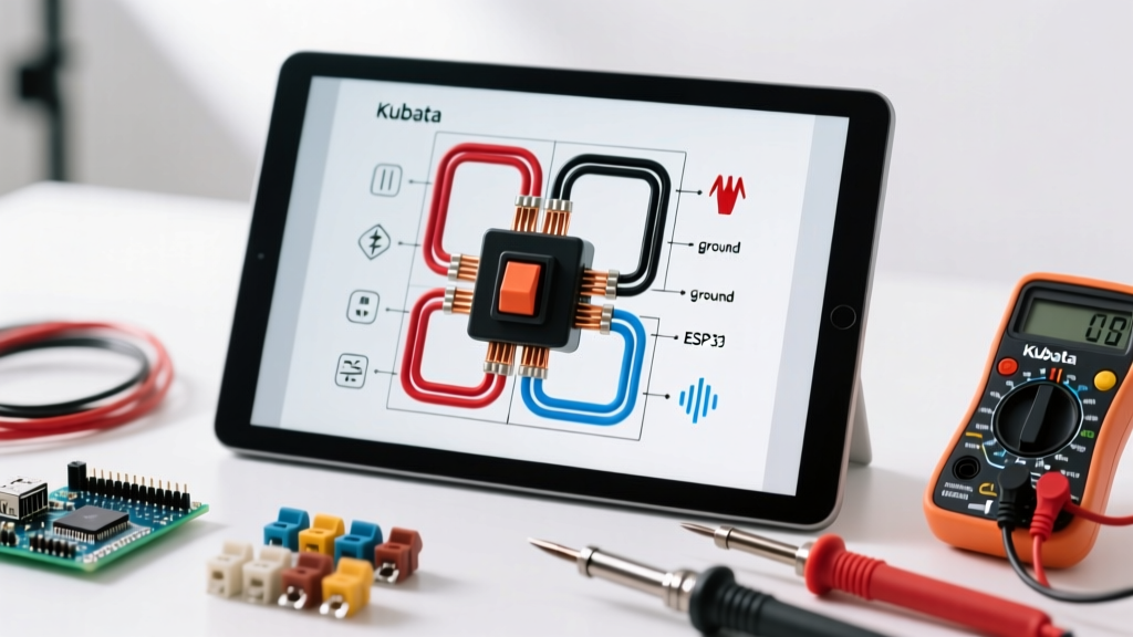
When transitioning from residential electrical work to agricultural and mobile machinery, DIYers and technicians quickly realize that the National Electrical Code (NEC / NFPA 70) no longer applies. If you are troubleshooting a heavy-duty tractor, interpreting an ignition switch electrical Kubota wiring diagram PDF requires a fundamental shift in how you understand circuits, environmental protection, and overcurrent standards. Modern Kubota models, ranging from the compact BX2380 to the industrial M7-172, utilize complex 12V DC architectures where the ignition switch acts as the primary logic gate for high-amperage relays and sensitive telematics modules.
In 2026, the integration of GPS auto-steer and IoT engine telemetry means the ignition bus carries more than just starter solenoid signals; it powers sensitive ECU wake-up circuits. Misinterpreting a wiring schematic can lead to catastrophic voltage drops, parasitic draws that kill batteries overnight, or melted harnesses. This guide breaks down the specific code requirements, terminal designations, and physical wiring standards necessary to safely execute repairs based on official Kubota PDF schematics.
The Regulatory Landscape: SAE vs. NEC Standards
Residential switches are governed by UL 1054 and NEC Article 404. However, mobile agricultural equipment falls under the jurisdiction of SAE International and ISO standards. When you download a factory service manual (WSM) schematic, the wire gauges, insulation types, and switch tolerances are engineered to meet these specific mobile codes:
- SAE J563 (Ignition Switches): Dictates the mechanical and electrical endurance of the switch. It requires the switch to withstand specific vibration profiles (up to 10G) and thermal cycling from -40°C to 85°C without internal contact arcing.
- SAE J1128 (Low Tension Cable): Governs the wire insulation seen in Kubota diagrams. Unlike residential THHN wire, SAE J1128 wire features thin-wall cross-linked polyethylene (XLPE) insulation rated for high heat and chemical resistance (diesel, hydraulic fluid).
- IP69K Ingress Protection: Modern Kubota ignition switches must survive high-pressure, high-temperature washdowns. A standard IP65 switch will fail prematurely in agricultural environments; OEM replacements must carry the IP69K rating.
Code Insight: While NFPA 79 covers stationary industrial machinery, mobile off-road equipment strictly adheres to SAE and ISO 14982 standards for electromagnetic compatibility (EMC) and wiring practices. Never substitute residential AC-rated toggle switches for DC mobile ignition circuits.
Decoding Terminal Designations in Kubota PDF Schematics
The most common point of failure when reading an ignition switch electrical Kubota wiring diagram PDF is misidentifying the switch terminals. Kubota typically uses a standardized alphanumeric coding system on the back of their 4-pin, 5-pin, and 6-pin ignition cylinders. Below is the master reference table for translating these PDF schematic nodes to physical switch posts.
| Terminal Code | Function in Kubota Schematic | Typical Wire Color | Max Amperage (Continuous) | Code/Standard Note |
|---|---|---|---|---|
| B (Battery) | Main 12V+ Input from Starter Solenoid | Red (Often 10 AWG) | 30A - 50A | Requires SAE J1127 battery cable if run direct. |
| S (Start) | Engages Starter Solenoid (Crank Position) | Yellow/Red Stripe | 15A (Momentary) | Must handle high inrush current to solenoid coil. |
| M (Motor/Run) | Powers ECU, Fuel Shutoff, and Dash in 'ON' | White or Black | 20A | Feeds main ignition relay; do not wire direct to loads. |
| G (Ground) | Switch Housing Ground / Illumination Return | Black | 5A | Required for LED dash illumination circuits. |
| L (Lamps) | Dash and Gauge Illumination Feed | Blue or Green | 5A | Often fused separately on the main fuse block. |
| H (Headlights) | Direct Headlight Power (Older Models) | Red/White | 15A | Newer models use a relay triggered by the 'M' terminal. |
Identifying OEM vs. Aftermarket Pinouts
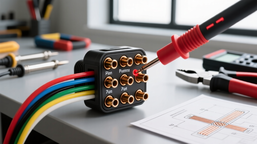
When sourcing a replacement, an OEM Kubota switch (e.g., part number 16231-63112 or 3C103-63110, typically priced between $85 and $145) will strictly match the WSM PDF. Aftermarket alternatives ($35 to $60) often rearrange the physical location of the 'S' and 'M' terminals on the bakelite housing. Always perform a bench continuity test with a multimeter before installing an aftermarket unit, regardless of what the packaging claims.
Code-Compliant Wire Sizing and Overcurrent Protection
A frequent error made by DIYers interpreting these PDFs is applying NEC AC voltage drop calculations to 12V DC systems. In a 120V AC home circuit, a 2-volt drop is negligible. In a 12V DC Kubota system, a 2-volt drop represents a 16% loss, which will cause the ECU to brown out and the starter solenoid to chatter violently.
Calculating DC Voltage Drop for Ignition Feeds
According to SAE guidelines, the maximum allowable voltage drop across the ignition switch and its primary feed wire should not exceed 0.1V under continuous load, and 0.5V during momentary cranking loads. When the PDF shows a 10 AWG wire running from the starter lug to the 'B' terminal, you must account for the total round-trip circuit length.
- Measure the Exact Run: Include the distance from the battery to the starter, plus the starter to the ignition switch.
- Apply the DC Multiplier: For a 20A continuous load on the 'M' terminal over a 10-foot run, 12 AWG wire will yield a 0.4V drop. You must step up to 10 AWG to achieve the SAE-compliant 0.2V drop.
- Fuse Placement: The PDF will show a main fusible link (typically 40A or 50A) located within 18 inches of the battery positive terminal. Never bypass this fusible link with a standard automotive blade fuse; blade fuses lack the interrupt capacity (AIC) to safely stop a dead-short fire on a heavy-gauge battery feed.
Step-by-Step: Translating the PDF Diagram to Physical Wiring
Follow this structured workflow to ensure your physical wiring matches the schematic while adhering to mobile electrical assembly standards.
1. Verify the Schematic Revision
Kubota frequently updates harness routing mid-production year. Ensure your PDF matches the exact serial number break of your tractor. You can verify the correct manual via the Kubota Service Portal using your chassis serial number.
2. Execute IPC/WHMA-A-620 Compliant Crimps
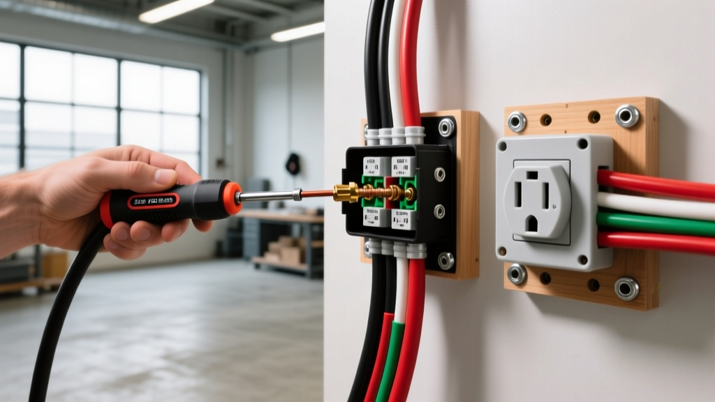
Soldering is strictly prohibited in high-vibration mobile environments because solder wicks into the wire strands, creating a rigid point that will snap under engine vibration. You must use open-barrel or closed-barrel crimp terminals. The crimp must pass the visual inspection criteria of the IPC/WHMA-A-620 standard: the wire strands must be visible at the front of the terminal barrel, and the insulation support must grip the wire jacket without pinching the copper.
3. Implement Deutsch or Weather-Pack Connectors
Never use butt-splices and electrical tape in the engine bay. The PDF will indicate multi-pin connectors (often designated as CN-1, CN-2, etc.). When repairing these nodes, use heat-shrink sealed crimps with dual-wall adhesive lining to maintain the IP67 waterproof rating of the harness.
Common Failure Modes and Troubleshooting Edge Cases
Even with a perfect understanding of the ignition switch electrical Kubota wiring diagram PDF, physical degradation can cause phantom issues. Here are the most common edge cases encountered in the field:
- The 'S' Terminal Parasitic Draw: If the internal return spring on the ignition cylinder weakens, the switch may not fully rotate back to the 'OFF' position. The 'S' terminal remains microscopically engaged, sending a 2A continuous draw to the starter solenoid. This will drain a 500CCA battery in 48 hours and overheat the solenoid coil. Fix: Test voltage at the solenoid trigger wire with the key removed; it must read exactly 0.00V.
- Telematics Brown-Outs: On 2024-2026 Kubota models equipped with factory GPS, the 'M' terminal powers the ECU wake-up relay. If the switch contacts are pitted from years of arcing, the resistance increases. Under load, the voltage at the ECU drops below 9.5V, causing the telematics module to reboot endlessly. Fix: Measure voltage drop directly across the B and M terminals while the key is ON. A reading above 0.15V indicates internal switch failure, regardless of external wire condition.
- Grounding via the Dash Panel: Older L-series tractors often rely on the metal dash panel to ground the 'G' terminal. Rust and dielectric grease can break this path, causing the dash lights to backfeed through the ECU data bus. Fix: Always run a dedicated 16 AWG ground wire from the switch 'G' terminal to a verified clean chassis ground, bypassing the dash panel entirely.
Sourcing and Verifying Authentic Schematics
Downloading random PDFs from third-party tractor forums is a significant cybersecurity risk and often results in outdated or incorrect schematics. Malicious PDFs can exploit vulnerabilities in outdated reader software. Always source your ignition switch electrical Kubota wiring diagram PDF directly from official Kubota dealer portals, verified factory service manual (WSM) repositories, or authorized agricultural technical databases. Cross-reference the wire color codes in the PDF with the physical harness; if the PDF shows a Yellow/Red wire but the tractor features a solid Blue wire, you are likely looking at a schematic for a different market region or an earlier production run.
Final Safety Directives
Working on mobile DC systems requires the same respect for arc-flash and short-circuit hazards as high-voltage AC work. Always disconnect the negative battery terminal before probing the ignition switch harness. Use a high-impedance digital multimeter (minimum 10 Megohm input impedance) to prevent back-feeding sensitive Kubota ECU circuits during continuity tests. By strictly adhering to SAE mobile codes and meticulously following the factory PDF schematic, you ensure the longevity, safety, and reliability of your equipment's electrical architecture.