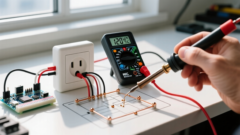

Why a Digital Multimeter Beats a Standard Receptacle Tester
When validating a newly installed 120V duplex receptacle or troubleshooting a dead circuit, many DIYers reach for a cheap, three-light neon receptacle tester. While these plug-in testers are fine for a superficial check, they cannot quantify voltage drop, identify high-resistance grounds, or reliably detect 'bootleg' grounds. Learning how to test electrical outlet with multimeter instrumentation provides exact, actionable data. A digital multimeter (DMM) measures the precise electrical potential difference between conductors, allowing you to verify compliance with the National Electrical Code (NEC) and ensure the safety of sensitive electronics.
Safety Warning: Always assume a circuit is live until proven otherwise. According to the Occupational Safety and Health Administration (OSHA), electrical testing requires appropriate Personal Protective Equipment (PPE) and tools rated for the environment. Never use a multimeter lacking the proper CAT rating for branch circuit testing.
Essential Gear: Selecting the Right Multimeter for 120V Diagnostics
Before inserting probes into a live NEMA 5-15R receptacle, you must verify your tool's safety rating. For standard residential and commercial 120V/208V branch circuits, your multimeter must be rated at least CAT III 600V. This rating ensures the internal components can withstand high-energy transient voltage spikes (arc flashes) that occur when testing at the panel or receptacle level.
- Premium Choice: Fluke 117 True-RMS Multimeter (~$210). Features 'LoZ' (Low Impedance) mode, which is critical for eliminating phantom voltages and identifying false series connections.
- Budget/Prosumer Choice: Klein Tools MM400 (~$50). A reliable CAT III 600V meter that provides accurate AC voltage readings, though it lacks LoZ and True-RMS capabilities.
- Probe Accessories: Use silicone-insulated test leads with finger guards to prevent accidental slippage onto adjacent hot terminals.
Pre-Testing Visual Inspection and Torque Verification
Before applying power and testing with a multimeter, a proper installation requires a physical inspection. If you are testing a newly installed outlet (such as a Leviton T5262 15A or Eaton 215W 20A commercial grade receptacle), verify the following:
- Wire Strip Length: Ensure no bare copper is exposed outside the terminal yoke. The NEC mandates that insulation must be flush with the terminal contact.
- Terminal Torque: NEC 110.14(D) requires the use of a calibrated torque screwdriver for new installations. Most 15A/20A receptacles require between 0.4 in-lbs and 1.2 in-lbs of torque. Hand-tightening can lead to thermal expansion failures over time.
- Grounding Pigtails: Verify that the equipment grounding conductor (EGC) is securely bonded to both the metal junction box (if applicable) and the receptacle's green grounding screw.
Step-by-Step Guide: How to Test Electrical Outlet With Multimeter
Follow this precise sequence to validate the wiring topology of a standard 120V, 3-prong outlet. Ensure your multimeter's black lead is plugged into the COM jack and the red lead is in the VΩ (Voltage/Ohms) jack.
Step 1: Configure the Multimeter for AC Voltage
Turn the rotary dial to V~ (AC Voltage). Do not use the DC voltage setting (V⎓), as residential branch circuits utilize alternating current. If your meter is not auto-ranging, manually select the 200V or 600V AC range to accommodate the expected 120V nominal supply.
Step 2: Test Hot to Neutral (The Baseline Voltage)
Insert the red probe into the shorter, hot slot (usually the right side, connected to the brass terminal). Insert the black probe into the longer, neutral slot (left side, connected to the silver terminal).
- Expected Reading: 115V to 125V.
- Analysis: This confirms the circuit breaker is energized and the neutral return path is intact. If the reading is below 110V, you may have excessive voltage drop due to undersized wiring or an overloaded circuit. The NEC recommends a maximum voltage drop of 3% on branch circuits (3.6V on a 120V system).
Step 3: Test Hot to Ground (Verifying the Safety Path)
Keep the red probe in the hot slot. Move the black probe to the U-shaped equipment grounding hole at the bottom of the receptacle.
- Expected Reading: 115V to 125V (typically identical or within 0.5V of the Hot-Neutral reading).
- Analysis: This confirms that the equipment grounding conductor is properly bonded back to the main panel's neutral-ground bus bar. A reading of 0V here indicates an open ground, which is a severe shock hazard and a violation of NEC Article 250.
Step 4: Test Neutral to Ground (Hunting for Voltage Drop and Bootlegs)
Move the red probe to the neutral slot (long slot) and keep the black probe in the ground hole.
- Expected Reading: 0.0V to 2.0V.
- Analysis: In a perfectly balanced, unloaded circuit, neutral and ground are at the same potential (0V difference). However, under load, current flowing through the neutral wire creates a slight voltage drop. A reading between 0.5V and 2.0V is normal and indicates a healthy, separate neutral and ground path. A reading of exactly 120V indicates reversed polarity (hot and neutral are swapped). A reading of 0.0V under heavy load could indicate a 'bootleg ground' (see Edge Cases below).
Diagnostic Matrix: Interpreting Your Multimeter Readings
Use this troubleshooting matrix to quickly diagnose wiring faults based on your multimeter's AC voltage readings.
| Hot-Neutral | Hot-Ground | Neutral-Ground | Diagnosis & Required Action |
|---|---|---|---|
| ~120V | ~120V | < 2.0V | Normal / Correctly Wired. Circuit is safe and code-compliant. |
| ~120V | 0V | 0V | Open Ground. The grounding wire is disconnected. Do not use for 3-prong appliances. |
| ~120V | ~120V | ~120V | Open Neutral. Neutral wire is broken or disconnected at the panel/receptacle. |
| ~120V | 0V | ~120V | Reversed Hot and Neutral. Wiring is swapped on the receptacle terminals. Immediate correction required. |
| 0V | 0V | 0V | Dead Circuit. Tripped breaker, tripped upstream GFCI, or open hot wire. |
Advanced Edge Cases: Phantom Voltages and Bootleg Grounds
When testing older homes or complex multi-wire branch circuits (MWBCs), you may encounter anomalous readings that confuse standard plug-in testers.
The 'Bootleg Ground' Deception
A bootleg ground occurs when an unscrupulous installer places a jumper wire between the neutral (silver) terminal and the ground (green) screw on the receptacle itself. This is done to trick standard 3-light neon testers into showing a 'correct' wiring status. This is incredibly dangerous. If the neutral wire breaks upstream, the metal chassis of any plugged-in appliance will become energized at 120V.
How to detect it with a multimeter: If your Neutral-to-Ground reading is exactly 0.0V even when a heavy load (like a hairdryer or vacuum) is running on the circuit, suspect a bootleg ground. To confirm, turn off the breaker, remove the receptacle faceplate, and visually inspect for a jumper wire between the silver and green screws.
Phantom Voltages and LoZ Mode
If you test a dead outlet and your multimeter reads 40V to 70V between Hot and Neutral, you are likely measuring 'phantom' or 'ghost' voltage. This happens when a de-energized wire runs parallel to a live wire in the same Romex cable, inducing a harmless electromagnetic voltage. Standard high-impedance digital multimeters will display this ghost voltage. If you are using a Fluke 117, switch to LoZ (Low Impedance) mode. LoZ introduces a small resistive load into the circuit, instantly draining phantom capacitance and dropping the reading to a true 0V.
Post-Testing Protocol and NEC Compliance
Once your multimeter confirms the outlet is wired correctly and voltage drop is within acceptable limits, finalize the installation. If you are replacing an ungrounded 2-prong outlet with a 3-prong receptacle, remember that NEC Article 406.4(D)(2) strictly prohibits creating a new ground path using the conduit or a cold water pipe unless specifically bonded per Article 250. Instead, you must install a GFCI receptacle and label it 'No Equipment Ground' to provide shock protection without a physical ground wire.
Mastering how to test electrical outlet with multimeter tools elevates your electrical work from guesswork to verified, professional-grade diagnostics. Always prioritize safety, use CAT-rated equipment, and consult the latest NEC guidelines for any permanent wiring modifications.