
Why Your New Electrical Outlet Has No Power
You just spent $4.50 on a Leviton T5320-W 15-Amp Tamper-Resistant duplex receptacle, carefully stripped your 14 AWG solid copper wires, and secured them to the terminal screws. You walk back to the panel, flip the breaker on, plug in your phone charger, and... nothing. Dealing with an electrical outlet no power scenario immediately after a fresh installation is one of the most frustrating hurdles for beginner DIYers. But before you rip open the drywall looking for a severed cable, take a breath. In 95% of cases, the issue is a localized wiring error at the terminal, a misconfigured upstream protection device, or a simple switched-loop oversight.
In this beginner installation tutorial, we will systematically diagnose and repair a dead receptacle. We will cover specific failure modes, the exact diagnostic tools you need in 2026, and step-by-step troubleshooting procedures to get your circuit live safely.
The 5 Most Common Reasons for Post-Installation Power Failure
When a newly wired receptacle fails to deliver 120V, the root cause almost always falls into one of these five categories:
- Upstream GFCI Tripped: Modern building codes require Ground Fault Circuit Interrupter (GFCI) protection in kitchens, bathrooms, garages, and outdoor areas. If your new outlet is wired to the 'LOAD' terminals of an upstream GFCI receptacle, and that upstream device has tripped, your new outlet will be dead.
- Backstab Connector Failure: Many beginners use the push-in 'backstab' holes on the back of the receptacle instead of the side terminal screws. These internal brass spring tangs are notorious for losing their grip, especially with stiff 12 AWG wire, leading to an immediate open circuit.
- Reversed Line/Load on GFCI: If you are installing a GFCI receptacle (like the Leviton SmartlockPro) and you accidentally wire the incoming power to the 'LOAD' terminals instead of the 'LINE' terminals, the device will not power up or reset.
- The 'Switched' Tab Was Not Removed: In living rooms and bedrooms, it is common to have a 'half-hot' outlet where the top plug is controlled by a wall switch. If you replaced an old half-hot receptacle but forgot to snap off the brass connecting fin between the top and bottom brass screws, the outlet will only work when the wall switch is on.
- Loose Neutral in the Panel: If you turned off the main breaker to install a new circuit or pigtail a neutral bus bar, a loose neutral connection will prevent the 120V circuit from completing its return path, resulting in zero usable power at the receptacle.
Essential Diagnostic Tools for 2026
Guesswork is dangerous when working with 120V AC mains. To properly troubleshoot an electrical outlet no power issue, you need reliable testing equipment. Here is the baseline toolkit for modern residential troubleshooting:
| Tool | Recommended Model (2026) | Avg. Price | Primary Use Case |
|---|---|---|---|
| GFCI Receptacle Tester | Klein Tools RT250 | $38.00 | Verifies wiring sequence and trips upstream GFCIs to test protection. |
| Non-Contact Voltage Tester | Fluke 2AC-II VoltAlert | $32.00 | Quickly checks for the presence of AC voltage through wire insulation. |
| Digital Multimeter (DMM) | AstroAI DM6000AR (True-RMS) | $35.00 | Measures exact AC voltage between hot, neutral, and ground terminals. |
| Wire Striper/Crimper | Klein Tools 11063W (Katapult) | $28.00 | Ensures precise 3/4-inch stripping without nicking the copper conductor. |
Step-by-Step Tutorial: Restoring Power to a Dead Outlet
Follow this systematic sequence to isolate and fix the fault. Always verify power is off before touching bare wires.
Step 1: Verify Panel and Upstream Protection Status
Before opening the receptacle box, walk the house. Check your main electrical panel for a tripped AFCI/GFCI breaker (the breaker handle will sit in the middle 'tripped' position; you must turn it fully OFF before pushing it ON). Next, check all other outlets in the room and adjacent rooms. Press the 'RESET' button on any GFCI receptacles you find. According to the ESFI GFCI resource page, daisy-chained outlets will remain dead until the primary upstream GFCI node is manually reset.
Step 2: Test for Voltage at the Receptacle Box
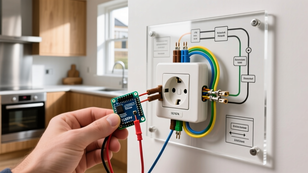
Remove the faceplate and unscrew the receptacle from the junction box. Pull it out gently without touching the bare side terminals. Turn the breaker back on. Set your True-RMS multimeter to AC Voltage (V~).
- Place the black probe on the bare copper ground wire and the red probe on the brass (hot) terminal. You should read between 118V and 122V.
- If you read 0V, the hot wire is disconnected upstream or the breaker is off.
- If you read 120V from Hot to Ground, but 0V from Hot to Neutral, you have an open neutral. This is a classic sign of a failed backstab connection on the white wire.
Step 3: Inspect and Repair Terminal Connections
Turn the breaker OFF again. Inspect your wire terminations. If you used the push-in backstab holes, pull the release tab with a small flathead screwdriver to free the wires. Never reuse a backstab connection once it has been released.
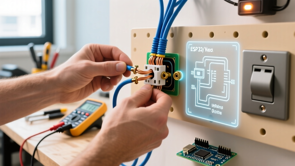
Instead, use the side terminal screws. Ensure your wire is stripped to exactly 3/4 of an inch. Form a 'J-hook' with needle-nose pliers and loop the wire clockwise around the screw. This ensures that as you tighten the screw (torque to roughly 12-14 inch-pounds), the loop pulls tighter rather than pushing out. Wrap the black (hot) wire to the brass screw, and the white (neutral) wire to the silver screw.
Step 4: Check the Switched Tab Configuration
If your outlet is in a living room and controlled by a wall switch, look at the brass side of the receptacle. There is a small metal connecting fin between the top and bottom brass screws. If the old outlet was half-hot, this fin was broken off. If you installed a new receptacle and left the fin intact, the switched leg and the constant hot leg are now shorted together, which will instantly trip the breaker. Use diagonal cutters to snap this fin off if your wiring diagram requires a split-wired receptacle.
Troubleshooting Matrix: Symptom vs. Solution
Use this quick-reference matrix to pinpoint your specific electrical outlet no power scenario based on multimeter readings and physical symptoms.
| Observed Symptom | Multimeter Reading (Hot to Neutral) | Most Likely Culprit | Corrective Action |
|---|---|---|---|
| Receptacle tester shows 'Open Neutral' | 120V Hot-to-Ground, 0V Hot-to-Neutral | White wire disconnected or failed backstab | Move neutral wire to side silver screw; check upstream wire nuts. |
| Tester shows 'Hot/Neutral Reverse' | 120V, but tester lights indicate reverse polarity | Black wire on silver screw, White on brass | Swap the wires. Black/Red to Brass; White to Silver. |
| GFCI button won't stay depressed | 0V across all terminals | Line and Load terminals reversed on GFCI | Move incoming power to 'LINE' terminals, downstream to 'LOAD'. |
| Breaker trips instantly upon reset | N/A (Breaker won't hold) | Hot-to-Ground short or broken brass tab on split outlet | Inspect for bare copper touching the metal box; remove brass fin. |
Safety, NEC Code Compliance, and Final Thoughts
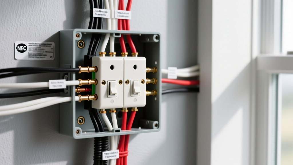
When replacing or installing new receptacles in 2026, you must adhere to the latest National Electrical Code (NEC) standards. The NEC mandates that all 15A and 20A, 125V receptacles installed in dwelling units must be Tamper-Resistant (TR). These feature internal plastic shutters that prevent children from inserting foreign objects into the slots. If you are struggling to plug a device into a new TR outlet, do not force it or break the shutters; insert the plug prongs perfectly straight and apply firm, even pressure.
Safety Warning: According to the NFPA electrical safety guidelines, working inside an electrical panel or handling exposed mains wiring without proper PPE and voltage verification is a leading cause of residential arc flash injuries. If you trace your 'no power' issue back to the main panel bus bar and feel uncomfortable, stop immediately and hire a licensed electrician. The CPSC electrical safety center strongly advises against DIY panel work for untrained individuals.
Diagnosing an electrical outlet no power issue after a fresh installation is rarely a sign of a catastrophic wiring failure. By methodically checking upstream GFCI resets, abandoning push-in backstab connectors in favor of secure side-screw terminations, and verifying your line/load configurations with a True-RMS multimeter, you can confidently restore power to your circuit. Take your time, double-check your wire strip lengths, and always test before you button up the drywall.