
The Complexity of 3-Way Dimming Circuits
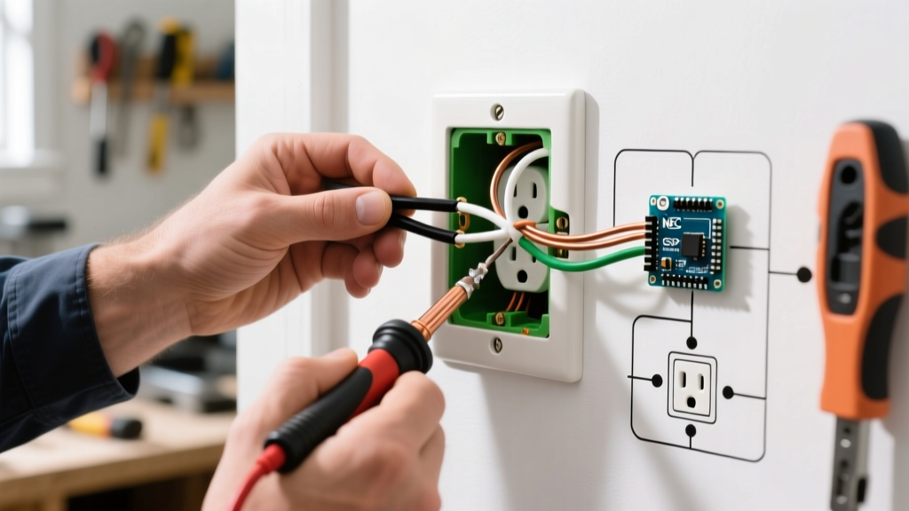
Upgrading a standard hallway or stairwell lighting circuit to include dimming capabilities requires more than just swapping a toggle for a dial. When studying a wiring diagram for 3 way switch with dimmer setups, electricians and advanced DIYers quickly realize that traveler wires, line/load identification, and modern LED compatibility introduce unique variables. Unlike single-pole installations, a 3-way circuit divides the switching logic across two physical locations. Integrating a dimmer into this architecture demands precise tool selection, code-compliant materials, and a flawless understanding of current flow.
This comprehensive tool and material guide provides the exact equipment specifications, product recommendations, and wiring logic required to execute a safe, flicker-free 3-way dimmer installation in 2026.
Essential Tools for 3-Way Dimmer Installation
Working inside crowded 3-gang or multi-gang switch boxes requires precision tools. Standard wire strippers often nick the copper conductor when working with 14 AWG or 12 AWG solid wire, leading to hot spots and eventual failure. Equip your pouch with the following professional-grade tools:
- Klein Tools 11055 Wire Strippers: Specifically calibrated for 14-22 AWG solid and stranded wire. The precision shear prevents conductor scoring, which is critical when bending wires into tight junction boxes.
- Fluke T5-600 Electrical Tester: Combines non-contact voltage detection with open-jaw current measurement. This allows you to verify the absence of voltage on the line and traveler wires without exposing bare copper to standard two-prong testers.
- Wago 221 Lever-Nuts (413 Series): Traditional twist-on wire nuts can fail in crowded 3-way boxes where wires are aggressively folded. Wago 221-413 lever connectors accommodate three 12-24 AWG conductors, providing a gas-tight, vibration-proof connection that saves up to 30% of box volume.
- Milwaukee 48-22-2922 Compact Magnetic Driver: The 1/4-inch hex shank and magnetic tip are essential for driving terminal screws in deep, poorly lit switch boxes where standard screwdrivers slip off the brass traveler terminals.
Material Selection: Dimmer Kits & Wire
Choosing the correct dimmer is paramount. Standard 3-way dimmers cannot be placed at both ends of a circuit without specialized companion switches. Below is a comparison of the top-rated 3-way dimming solutions available on the market, categorized by their architectural requirements.
| Product Model | Type | Neutral Required? | Est. Price (2026) | Best Application |
|---|---|---|---|---|
| Lutron Diva DV-603P | Standard 3-Way | No | $32 - $38 | Legacy homes lacking neutral wires at the switch box. |
| Leviton Decora Smart DW6HD | Wi-Fi Smart 3-Way | Yes | $55 - $65 | Smart home integration; requires companion app or remote switch. |
| Eaton Universal HALO HED | Universal (ELV/MLV) | Yes | $60 - $75 | Mixed lighting loads (LED, CFL, Halogen) on a single circuit. |
Note: If your circuit utilizes low-voltage LED tape lighting with a magnetic transformer, you must select an MLV (Magnetic Low Voltage) compatible dimmer like the Eaton HED to prevent transformer buzzing and premature failure.
Decoding the Wiring Diagram for 3 Way Switch with Dimmer
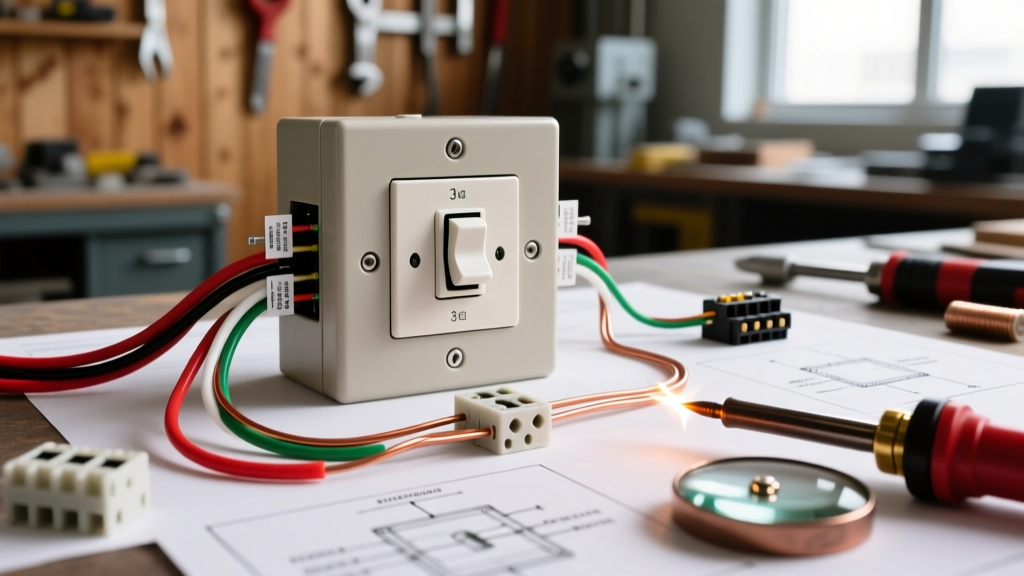
A standard 3-way circuit relies on a Common terminal and two Traveler terminals. When interpreting your wiring diagram, the fundamental rule is that the dimmer must replace only one of the two standard 3-way switches. The secondary location must remain a standard 3-way toggle, or utilize a proprietary companion switch if deploying a smart system.
Identifying Line, Load, and Travelers
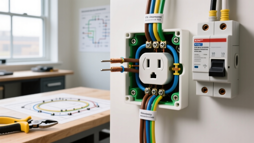
Before disconnecting any wires, map the circuit. The Line (incoming hot from the breaker) and the Load (outgoing hot to the light fixture) will each connect to the black or dark-colored 'Common' screw on their respective switches. The two Traveler wires (usually red and black, or red and white with black tape) run between the two switches and connect to the brass-colored terminals.
When installing the dimmer, its Common terminal must connect to either the Line or the Load, depending on which end of the circuit you are placing the dimmer. The dimmer's two brass traveler terminals will connect to the traveler wires. The physical placement of the travelers on the brass screws does not matter; they are interchangeable.
The Neutral Wire Requirement (NEC 404.2)
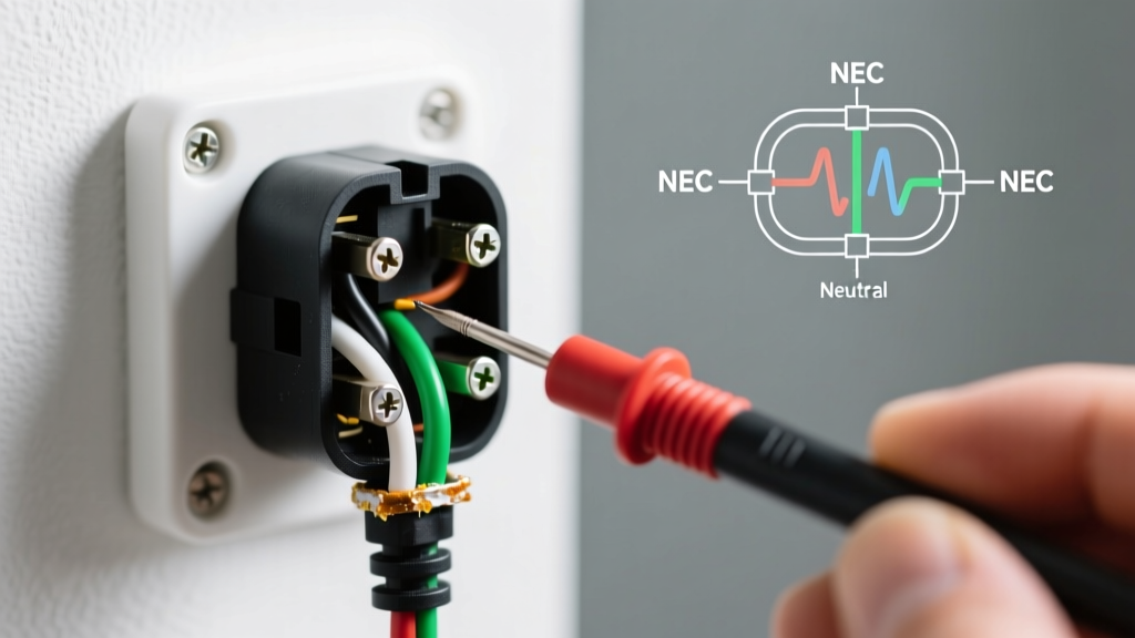
According to the National Fire Protection Association (NFPA) NEC Guidelines, Article 404.2(C) mandates that a grounded (neutral) conductor be present at nearly all switch locations. This is to accommodate smart switches and dimmers that require a continuous 120V return path for their internal logic boards.
If you are installing a smart 3-way dimmer (like the Leviton DW6HD), you must connect the dimmer's white neutral pigtail to the bundle of neutral wires in the back of the box. If your older home lacks a neutral wire at the switch location, you are legally and practically restricted to standard, non-smart analog dimmers like the Lutron DV-603P, which trickle a small amount of current through the load (the lightbulb) to power their internal circuitry.
Step-by-Step Physical Execution
Follow this sequence to ensure a safe, code-compliant installation. Always adhere to OSHA Electrical Safety Standards by verifying the breaker is locked out and tagged out (LOTO) before beginning.
- Kill the Power & Verify: Turn off the 15A or 20A breaker. Use the Fluke T5-600 to test the line, load, and traveler wires. A reading of 0V confirms the circuit is dead.
- Remove the Old Switch: Unscrew the mounting plate and pull the existing 3-way switch out. Take a photo of the wiring before disconnecting anything.
- Prep the Dimmer Pigtails: Strip exactly 1/2 inch of insulation from the dimmer's stranded pigtails using the Klein 11055. If connecting stranded dimmer wires to solid house wires, use Wago Lever-Nuts to prevent the stranded wire from fraying under a screw terminal.
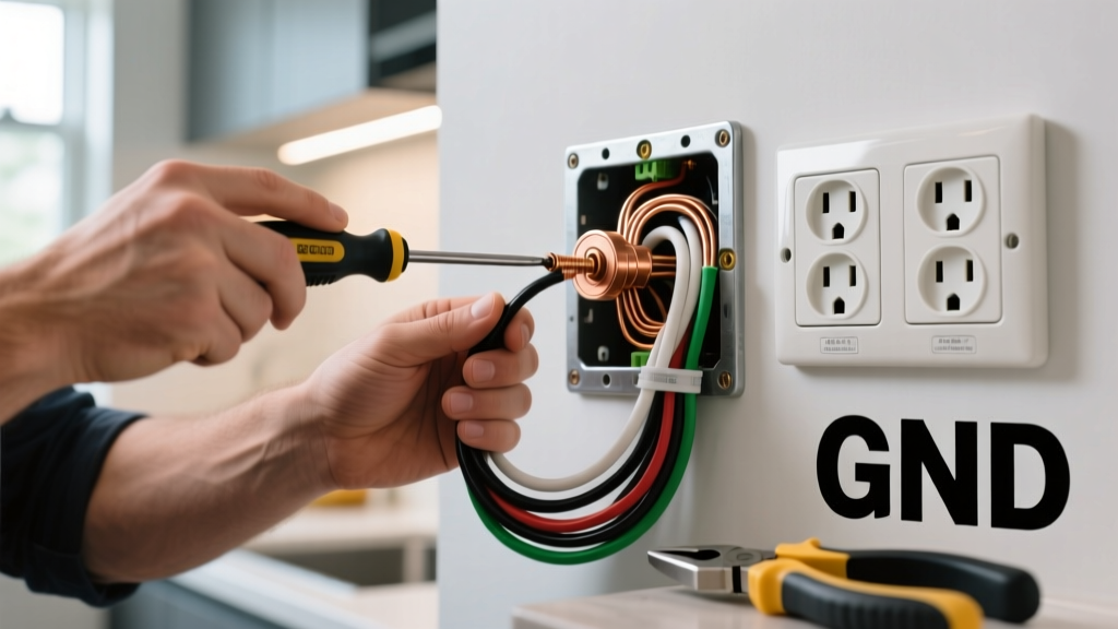
- Connect Ground: Connect the dimmer's green ground wire to the bare copper ground bundle and the metal box (if applicable) using a green wire nut or Wago connector.
- Connect Neutral (If Applicable): Connect the dimmer's white wire to the house's neutral bundle. Do not connect this to the ground wire.
- Connect Travelers & Common: Attach the two house traveler wires to the dimmer's brass terminals. Attach the house Line (or Load) wire to the dimmer's black Common terminal.
- Fold and Mount: Carefully fold the wires into the box, keeping the ground wires pushed to the back. Secure the dimmer with the provided mounting screws and attach the faceplate.
Advanced Troubleshooting & Edge Cases
Even with a perfect wiring diagram for 3 way switch with dimmer execution, modern LED lighting can introduce anomalous behaviors. Here is how to diagnose and resolve the most common edge cases:
1. LED Ghosting and Flickering at Low Levels
The Cause: Many older or budget dimmers leak a small amount of current to power their internal illuminated locator lights. Because LEDs draw so little power (often under 9W per bulb), this leakage current charges the LED's internal capacitor, causing it to flash or 'ghost' when turned off.
The Fix: Install a bypass capacitor, such as the Lutron LUT-MLC, across the load (at the light fixture, not the switch). Alternatively, upgrade to an advanced digital dimmer that utilizes a neutral wire, completely eliminating the need to leak current through the load.
2. Audible Buzzing from the Switch or Fixture
The Cause: Buzzing is typically a result of mismatched dimming technologies. Using a standard TRIAC (forward-phase) dimmer on a low-voltage LED system with an electronic transformer (ELV) causes severe harmonic distortion.
The Fix: Verify the transformer type. If it is ELV, you must use a reverse-phase (trailing-edge) dimmer. Refer to the U.S. Department of Energy Solid-State Lighting compatibility matrices to match your specific LED driver with a compatible trailing-edge dimmer.
3. The 'Pop' on Power-Up
The Cause: If the standard 3-way toggle is turned ON while the dimmer is set to its lowest physical position, some LED drivers will experience a massive inrush current spike, resulting in an audible 'pop' and reduced lifespan of the LED driver.
The Fix: Utilize a dimmer with 'soft-start' technology (standard on most Lutron and Leviton digital models), which ramps the voltage up over 0.5 seconds, protecting the solid-state drivers from inrush shock.
Frequently Asked Questions
Can I install two dimmers on a single 3-way circuit?
No. Placing two standard analog dimmers in series on the traveler wires will result in a short circuit, erratic voltage drops, and a severe fire hazard. If you require dimming control from both locations, you must purchase a specialized 'Master/Companion' smart switch system (e.g., Lutron Maestro or Caseta), where the master handles the actual voltage chopping, and the companion sends a low-voltage digital signal to the master via the traveler wires.
Do I need to re-wrap white traveler wires with black tape?
Yes. According to NEC color-coding standards, a white wire used as a hot traveler or line conductor must be permanently re-identified with black or red electrical tape at both termination points. This prevents future electricians from mistakenly assuming the white wire is a neutral and connecting it to the neutral bus bar, which would cause an immediate dead short.