
Understanding the Anatomy of a 3-Way Switch
Unlike a standard single-pole switch that simply breaks the hot wire, a 3-way switch is technically a Single-Pole, Double-Throw (SPDT) device. It routes the incoming hot current down one of two possible paths to the second switch. To successfully interpret any wiring diagram for three way light switch configurations, you must first identify the three critical terminals on the switch body. Whether you are installing a basic $4 Leviton Decora 5603-2W or a $65 Lutron Caséta smart switch, the fundamental terminal logic remains the same.
- Common Terminal (Dark/Black Screw): This is the electrical pivot point. On the first switch, the incoming hot (line) wire connects here. On the second switch, the outgoing hot (load) wire leading to the light fixture connects here.
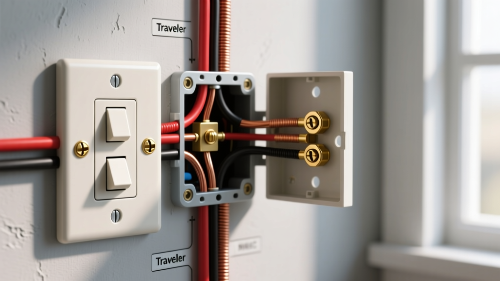
- Traveler Terminals (Brass/Lighter Screws): These two screws are functionally interchangeable. They connect to the red and black wires of the 3-conductor cable running between the two switches.
- Ground Terminal (Green Screw): Connects to the bare copper or green insulated equipment grounding conductor.
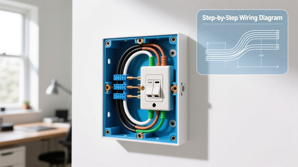
Standard Wiring Diagram for Three Way Light Switch (Power at Switch 1)
The most common residential configuration places the power source at the first switch box, runs a 3-conductor cable to the second switch, and then sends a 2-conductor load cable up to the light fixture. Below is the definitive connection matrix for this layout. In 2026, with copper prices stabilizing, standard 14/3 NM-B cable costs approximately $0.85 per foot, making it economical to pull new lines rather than attempting complex wireless relay bypasses.
Connection Matrix: Power Source at Switch 1
| Location | Wire / Cable | Wire Color | Connection Point |
|---|---|---|---|
| Switch 1 Box | 14/2 NM-B (Line) | Black (Hot) | Common Screw (Black) |
| Switch 1 Box | 14/2 NM-B (Line) | White (Neutral) | Wire nut to 14/3 White (Neutral pass-through) |
| Switch 1 Box | 14/3 NM-B | Red & Black | Brass Traveler Screws |
| Switch 2 Box | 14/3 NM-B | Red & Black | Brass Traveler Screws |
| Switch 2 Box | 14/3 NM-B | White (Neutral) | Wire nut to 14/2 Load White |
| Switch 2 Box | 14/2 NM-B (Load) | Black (Hot) | Common Screw (Black) |
| Light Fixture | 14/2 NM-B (Load) | White & Bare | Fixture Neutral & Ground |
Pro Tip: The white neutral wire from the power source must bypass Switch 1 entirely. Do not connect it to the switch. Use a Wago 221 3-conductor lever nut to splice the incoming neutral directly to the white wire of the 14/3 traveler cable heading to Switch 2.
Alternative Diagram: Power Source at the Light Fixture
When reviewing a wiring diagram for three way light switch setups where power enters at the ceiling fixture, the wiring logic shifts. The 14/2 power cable drops into the fixture box, and a 14/3 cable must drop from the fixture down to Switch 1. Another 14/3 cable runs between Switch 1 and Switch 2.
In this scenario, the white wire of the 14/3 cable dropping from the ceiling to Switch 1 is used as the hot feed down to the common terminal of Switch 1. According to NFPA 70 (National Electrical Code) Article 200.7(C)(1), any white wire used as a hot ungrounded conductor must be permanently re-identified. Wrap both ends of this white wire in black electrical tape or use a black Sharpie to indicate it is carrying line voltage, not neutral.
Connection Matrix: Power Source at Light Fixture
| Location | Wire / Cable | Wire Color | Connection Point |
|---|---|---|---|
| Fixture Box | 14/2 Power | Black (Hot) | Spliced to 14/3 White (Re-identified Black) |
| Fixture Box | 14/3 to Sw 1 | Black | Fixture Hot (Load) |
| Fixture Box | 14/3 to Sw 1 | Red | Spliced to 14/3 Red (Traveler to Sw 2) |
| Switch 1 | 14/3 from Ceiling | White (Taped Black) | Common Screw (Line In) |
| Switch 1 | 14/3 to Sw 2 | Black & Red | Brass Traveler Screws |
| Switch 2 | 14/3 from Sw 1 | Black & Red | Brass Traveler Screws |
| Switch 2 | 14/3 from Sw 1 | White (Neutral) | Capped off (Not used on standard switch) |
NEC Code Requirements & Smart Switch Upgrades
If you are upgrading to smart lighting in 2026, understanding the neutral wire requirement is critical. Modern smart switches, such as the Lutron Caséta PD-5S-DV or the Enbrighten Z-Wave Plus 3-Way, require a constant 120V neutral connection to power their internal Wi-Fi, Zigbee, or Z-Wave radios. This aligns with NEC Article 404.2(A), which mandates that a neutral conductor be present at almost all switch boxes in new construction.
If your existing wiring diagram for three way light switch circuits lacks a neutral at the second switch box (common in pre-2011 homes), you have two options:
- Use a Lutron Caséta Pico Remote: Wire the primary smart switch at the box that does have a neutral, and cap off the wires at the second box, installing a battery-powered Pico remote in the wallplate. This avoids tearing open drywall.
- Pull New Cable: Replace the 14/3 traveler cable with a 14/4 NM-B cable to ensure a dedicated neutral is present at both switch locations, future-proofing the circuit.
For comprehensive safety guidelines on residential wiring and arc-fault protection, always consult the U.S. Consumer Product Safety Commission (CPSC) Electrical Safety Guide before energizing new circuits.
Troubleshooting Common 3-Way Wiring Failures
Even experienced DIYers miswire traveler circuits. Use this diagnostic matrix to identify failure modes without guessing.
| Symptom | Probable Cause | Diagnostic Step |
|---|---|---|
| Light only turns on/off from Switch 1; Switch 2 does nothing. | The 'Line' hot wire is connected to a traveler screw on Switch 1 instead of the Common screw. | Verify the hot feed is on the dark/black screw. Use a non-contact voltage tester on the brass screws to confirm they are not the primary feed. |
| Light only works when BOTH switches are in the exact same physical position. | The load wire and a traveler wire are swapped on Switch 2. | Ensure the wire heading up to the ceiling fixture is on the Common (dark) screw of Switch 2. |
| Breaker trips immediately upon flipping either switch. | A hot traveler wire is shorted to ground, or the neutral is incorrectly bonded to a traveler. | Disconnect all wires, separate them, and use a multimeter in continuity mode to test for shorts between the black/red travelers and the bare ground wire. |
| Switch feels warm to the touch after 10 minutes. | Overloaded circuit (e.g., controlling exterior security lights exceeding 15 Amps) or loose side-wire termination causing high resistance. | Check total wattage. Ensure wire loops are tight and clockwise. For 12 AWG wire, use the push-in backwire clamp instead of side screws if available. |
Pro Tips for Clean Terminations
The longevity of your 3-way switch installation depends heavily on termination quality. Follow these specific measurement and technique guidelines:
- Strip Length: Use the strip gauge on the back of the switch. For Leviton Decora models, this is exactly 3/4 inch for side wiring and 1/2 inch for push-in backwiring. Stripping too much copper exposes live voltage; stripping too little causes the screw to bite into the wire insulation, leading to arcing.
- The Shepherd's Hook: When using side screws, bend the wire into a 'J' shape. Hook it around the screw clockwise. This ensures that tightening the screw pulls the wire loop tighter rather than pushing it out.
- Pigtailing Grounds: Never daisy-chain ground wires through the switch's green screw. Instead, use a wire nut or a Wago lever connector to join all bare copper grounds in the box, then run a single 6-inch pigtail to the switch's ground screw. This ensures the circuit remains grounded even if the switch is removed for painting.
- Box Fill Calculations: 3-way switch boxes often become crowded. A standard single-gang box (18 cubic inches) is easily overfilled when splicing 14/3 and 14/2 cables. Upgrade to a 22.5 cubic inch deep single-gang box (like the Carlon B618R-UPC) to provide adequate heat dissipation and physical space for Wago connectors.
Mastering the wiring diagram for three way light switch layouts requires patience and a methodical approach to wire identification. By strictly adhering to NEC color-coding rules, utilizing proper termination techniques, and referencing the connection matrices above, you can achieve a safe, code-compliant, and reliable multi-location lighting circuit.