
From 2D Vectors to Live Voltage: Mastering Outlet Schematics
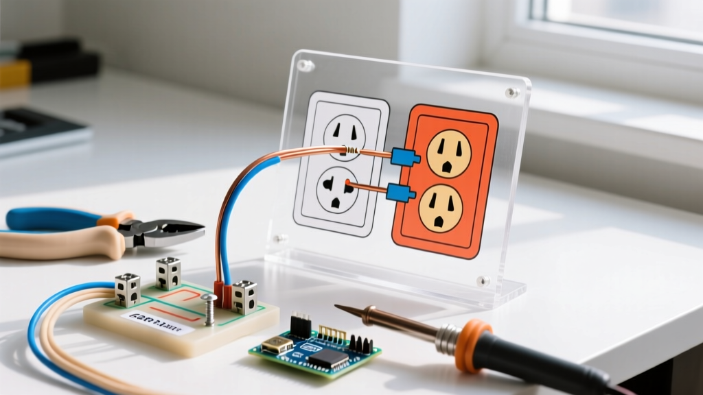
When visual learners, DIY bloggers, or trade instructors search for a clipart electrical outlet, they are usually looking for simplified, 2D vector representations of NEMA 5-15R receptacles. While these graphics are often used in presentations and safety manuals, they serve a much more critical purpose for beginners: they are the foundational blueprints for understanding circuit topology. Translating a flat, color-coded schematic into a physical, three-dimensional wiring installation is the first major hurdle for any aspiring DIY electrician.
In this 2026 beginner installation tutorial, we will bridge the gap between digital diagrams and physical reality. You will learn how to decode standard outlet clipart, map those symbols to a physical Leviton 5262 duplex receptacle, and execute a safe, code-compliant installation using 14 AWG or 12 AWG copper wire.
⚠️ CRITICAL SAFETY WARNING: Never begin physical installation based on a diagram without first verifying the circuit is dead. Always use a non-contact voltage tester (such as the Klein Tools NCVT-1, approx. $18) at the receptacle and the panel. According to the Electrical Safety Foundation International (ESFI), electrocution and arc flash risks remain the leading causes of severe DIY electrical injuries.
Decoding the Clipart Electrical Outlet Symbols
Standardized electrical clipart relies on a universal color and shape language dictated by the National Electrical Code (NEC). Before you strip a single wire, you must understand what the 2D graphic is telling you.
The Big Three: Hot, Neutral, and Ground
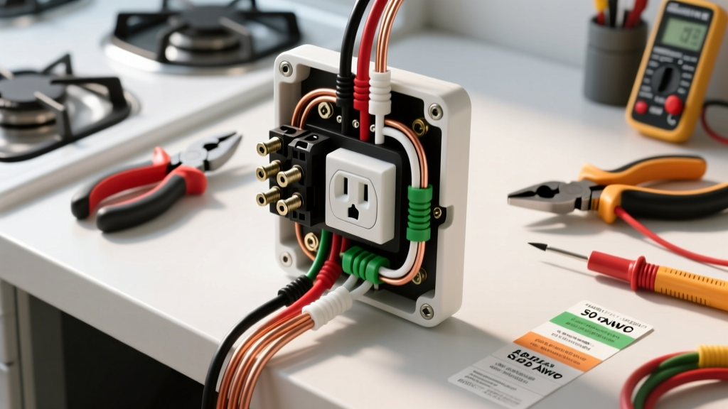
- The Ground (Green/Hexagon): In almost all schematic clipart, the ground is represented by a green wire terminating at a green, hexagon-shaped screw at the bottom of the yoke. This is your fault-current path.
- The Neutral (Silver/Long Slot): Depicted as a white wire connecting to a silver screw. On the physical outlet face, this corresponds to the longer vertical slot. It carries current back to the panel.
- The Hot (Brass/Short Slot): Depicted as a black (or red/blue) wire connecting to a brass screw. This aligns with the shorter vertical slot on the receptacle face and delivers 120V from the breaker.
The Break-Off Fins (Tabs)
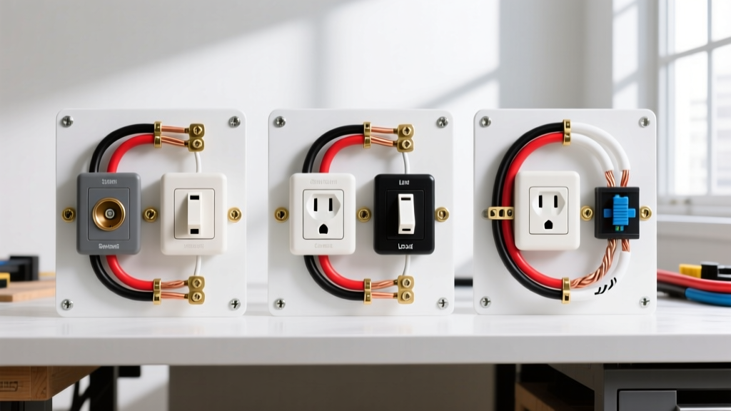
Most high-quality clipart diagrams will show a small metal bridge connecting the top and bottom brass screws, and another connecting the silver screws. These are the break-off tabs. In 90% of standard bedroom or living room installations, these tabs remain intact so that a single incoming hot wire powers both the top and bottom receptacles.
Step-by-Step: Translating 2D Diagrams to 3D Wiring
Let us translate our theoretical schematic into a physical installation using a standard 15-Amp, 125-Volt Tamper-Resistant (TR) duplex receptacle (e.g., Leviton 5262, approx. $1.50). As of the 2026 NEC cycle, TR receptacles are mandatory in virtually all residential living spaces to prevent childhood shock hazards via the internal shutter mechanism.
Step 1: Wire Preparation and Stripping
Diagrams rarely show strip lengths, but physical tolerances are unforgiving. Using a wire stripper (like the Gardner Bender GS-11), strip exactly 1/2 inch to 5/8 inch of insulation from your 14 AWG solid copper wire.
Pro Tip: Most modern receptacles feature a physical 'strip gauge' molded into the back plastic housing. Match your stripped wire to this gauge; exposed copper outside the terminal block is a severe shock and short-circuit hazard.
Step 2: Forming the J-Hook
Using needle-nose pliers, bend the stripped copper into a 'J' shape or shepherd's hook. The curve must be smooth—kinked or sharply creased copper creates a high-resistance hot spot that can melt the yoke over time.
Step 3: The Clockwise Connection
Hook the wire around the terminal screw in a clockwise direction. As you tighten the screw with a Robertson #2 square-head screwdriver, the clockwise motion pulls the loop tighter under the screw head. Counter-clockwise wrapping will push the wire out as the screw turns, a common beginner failure mode not always obvious in 2D clipart.
Step 4: Torque and Seating
Tighten the terminal screws until they are firmly seated. For standard 15A residential receptacles, Leviton and the NEC (Article 110.14) recommend a torque of approximately 14 in-lbs. If you are using a push-to-wire (backstab) connection instead of screw terminals—which many modern diagrams advise against for long-term reliability—ensure the wire is inserted fully until it clicks, and verify it cannot be pulled out with a firm tug.
Diagram Comparison: Standard Duplex vs. GFCI
When researching outlet schematics, you will inevitably encounter GFCI (Ground Fault Circuit Interrupter) diagrams. The physical wiring differs significantly from standard clipart models.
| Feature | Standard Duplex (NEMA 5-15R) | GFCI Receptacle (15A/20A) |
|---|---|---|
| Terminal Types | Brass (Hot), Silver (Neutral), Green (Ground) | LINE (Incoming Power), LOAD (Downstream Protection), Green (Ground) |
| Tab Configuration | Break-off fins on both Hot and Neutral sides | No break-off fins; uses internal circuitry for downstream protection |
| Wire Count (Basic) | 1 Hot, 1 Neutral, 1 Ground | 1 Hot (LINE), 1 Neutral (LINE), 1 Ground |
| Approx. Cost (2026) | $1.50 - $2.50 | $16.00 - $24.00 |
Common Beginner Mistakes When Reading Outlet Diagrams
Even the best vector graphics omit real-world edge cases. Avoid these frequent installation errors:
- Backstabbing vs. Screw Terminals: Many older diagrams show wires being pushed into the small holes on the back of the receptacle (backstabbing). While UL-listed, the internal spring-metal contacts degrade over decades, leading to arcing. Always use the side screw terminals or the 'back-wire' clamp plates found on higher-end commercial-grade receptacles (like the Leviton Pro Grade 5262-A).
- Over-tightening Ground Screws: The green ground screw is often softer than the brass/silver screws. Over-torquing can strip the threads or snap the screw head, requiring you to replace the entire $1.50 device.
- Ignoring Box Fill Calculations: Clipart diagrams show wires floating in a void. In reality, NEC Article 314.16 dictates strict 'box fill' limits. A standard single-gang plastic nail-on box (approx. 18 cubic inches) can comfortably hold one receptacle, two 14/2 NM-B cables, and the internal clamps. Stuffing three or four cables into this box causes wire pinching, damaging insulation and creating a short-circuit risk.
- Misidentifying the Switched Half: In living rooms, it is common for the top receptacle to be controlled by a wall switch, while the bottom is always hot. This requires physically snapping the brass break-off fin on the receptacle and running a 3-wire (14/3 NM-B) cable from the switch. Standard basic diagrams rarely cover this split-wired scenario.
Frequently Asked Questions (FAQ)
Can I use a 20A receptacle on a 15A breaker?
No. According to NEC Table 210.21(B)(3), a 15A circuit (using 14 AWG wire) can only accommodate 15A receptacles. However, a 20A circuit (using 12 AWG wire) can accommodate either 15A or 20A receptacles. Always match your breaker, wire gauge, and receptacle rating correctly.
Why do my outlet diagrams show a red wire?
In standard 14/3 or 12/3 NM-B (Romex) cable, the red wire is typically used as a secondary hot leg. This is common in Multi-Wire Branch Circuits (MWBC) or 3-way switch loops. If you see a red wire in a schematic, it indicates a split-receptacle or switch-loop configuration, not a standard single-pole plug-in outlet.
Do I need to pigtail the ground wire?
Yes. If you have multiple cables entering the box, you must wire-nut all the bare copper ground wires together along with a 6-inch 'pigtail' that connects to the receptacle's green screw. Never use the receptacle itself as the sole daisy-chain path for the ground fault current.
Final Thoughts on Schematic Planning
Using a clipart electrical outlet diagram is an excellent first step in visualizing your circuit before you ever turn off a breaker. By understanding the universal language of hot, neutral, and ground, and respecting the physical limitations of box fill and torque specifications, you transition from simply looking at pictures to executing safe, professional-grade electrical work. For further reading on residential code requirements, consult the National Fire Protection Association's NEC resources to ensure your 2026 installations remain fully compliant and safe for decades to come.