
Assessing Your Wiring Scenario: 15-Amp vs. 20-Amp Circuits
Before cutting into your drywall, you must determine the capacity of the existing circuit you plan to extend. In 2026, the most common residential wiring scenarios involve extending a 15-amp or 20-amp branch circuit from an adjacent receptacle or switch box. Overloading a 15-amp circuit by adding high-draw appliances is a leading cause of thermal degradation and breaker nuisance tripping.
| Circuit Rating | Wire Gauge (Copper) | Breaker Size | Receptacle NEMA Config | Common 2026 Material Cost | Best Use Case |
|---|---|---|---|---|---|
| 15-Amp | 14 AWG | 15A | 5-15R (Standard Duplex) | $3.50 - $5.00 | Bedrooms, living rooms, general lighting |
| 20-Amp | 12 AWG | 20A | 5-20R (T-Slot) or 5-15R | $4.50 - $7.00 | Kitchens, bathrooms, garages, workshops |
Expert Note: You can install a 15-amp receptacle on a 20-amp circuit (provided there are multiple receptacles on the circuit), but you cannot install a 20-amp receptacle on a 15-amp circuit. Always match or exceed the wire gauge of the existing circuit when extending.
Essential Tools and Materials for Old-Work Scenarios
Working inside finished walls requires specific 'old-work' (retrofit) components. Do not use new-work nail-on boxes, as they require exposed studs. Here is the precise bill of materials for a standard 1-gang outlet extension:
- Box: Carlon B114R 1-Gang 14 cu. in. Non-Metallic Old Work Box ($2.50). The 14 cubic inch volume is critical for NEC Article 314 box fill calculations when housing 14/2 or 12/2 NM-B cable with internal clamps.
- Receptacle: Leviton 5262-SW 15-Amp Tamper-Resistant (TR) Duplex Receptacle ($3.20). The 'TR' stamp is mandatory by code for all residential living spaces.
- Wire Strippers: Klein Tools 11055 Wire Stripper (Calibrated for 10-18 AWG solid/stranded).
- Fish Tape: Milwaukee 48-22-0100 50ft Steel Fish Tape for routing NM-B cable through wall cavities.
- Torque Screwdriver: Wiha 61100 VDE Torque Screwdriver (Required for 2023/2026 NEC 110.14(D) compliance).
- Tester: Klein Tools NCVT-2 Non-Contact Voltage Tester.
Step-by-Step Installation in an Existing Wall
Phase 1: Locating Power and Fishing the Cable
First, identify the donor box (the existing outlet or switch that will feed power to your new outlet). Turn off the breaker and verify the absence of voltage using your NCVT-2 tester on both the top and bottom terminal screws of the donor receptacle.
Remove the donor receptacle from the wall to expose the cavity. Use a stud finder to locate the studs between the donor box and your new outlet location. You will need to drill a 3/4-inch hole through the center of any intermediate studs using a flexible drill bit (like a Greenlee 830-972) attached to a right-angle drill. Feed your fish tape from the new outlet location to the donor box, attach your 14/2 or 12/2 NM-B cable, and pull it back through. Leave at least 8 inches of cable protruding from both boxes.
Phase 2: Drywall Cutting and Old-Work Box Mounting
Trace the face of your Carlon B114R old-work box onto the drywall at the new location. Cut the outline using a drywall jab saw. Before inserting the box, strip back 8 inches of the outer NM-B jacket using your Klein 11055 strippers, being careful not to nick the copper conductors or the paper separator.
Thread the stripped wires through the integrated cable clamps of the old-work box. Push the box into the drywall opening. As you tighten the two mounting screws on the face of the box, the internal PVC 'wing' flaps will rotate 90 degrees and clamp securely against the back of the drywall. Do not overtighten, or you will crush the drywall paper and compromise the box's stability.
Phase 3: Cable Stripping and Termination
Proper termination is where most DIY failures occur. Strip exactly 3/4 inch of insulation from the black (hot) and white (neutral) wires. Never use the push-in 'backstab' holes on the back of the receptacle. Spring-loaded backstab connectors are notorious for loosening over time due to thermal cycling, leading to high-resistance connections and arc faults.
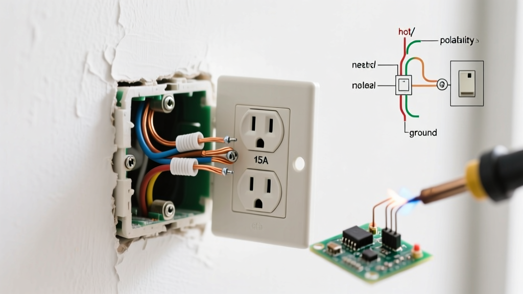
Instead, use the side-wiring terminal screws. Form a tight 'shepherd's hook' clockwise around the brass (hot) and silver (neutral) screws. According to NEC 110.14(D) and manufacturer specifications, you must tighten these screws to the listed torque value—typically 14 in-lbs for 14 and 12 AWG copper wire on Leviton residential devices. Use your calibrated torque screwdriver to ensure a gas-tight mechanical connection. Finally, loop the bare copper ground wire around the green grounding screw and secure it.
2026 NEC Code Compliance: GFCI, AFCI, and TR Requirements
Electrical codes have evolved significantly to mitigate fire and shock hazards. When learning how to install a new electrical outlet, you must adhere to the latest National Electrical Code (NEC) adoptions enforced in 2026.
- Tamper-Resistant (TR): All 15A and 20A receptacles in dwelling units must be TR type. These feature internal shutters that only open when equal pressure is applied to both slots simultaneously, preventing children from inserting foreign objects.
- GFCI Protection: The Consumer Product Safety Commission (CPSC) heavily mandates Ground Fault Circuit Interrupter protection in areas with water proximity. If your new outlet is in a kitchen, bathroom, garage, crawl space, basement, or within 6 feet of a wet bar sink, it must be GFCI protected. You can achieve this by installing a GFCI receptacle at the new location or wiring it to the 'LOAD' terminals of an upstream GFCI.
- AFCI Protection: Arc-Fault Circuit Interrupters are required for almost all living spaces (bedrooms, living rooms, hallways). If you are extending a circuit in these areas, the breaker in the main panel must be an AFCI type, or you must use a combination AFCI receptacle.
For comprehensive code standards, always refer to the National Fire Protection Association (NFPA) 70 NEC guidelines, which dictate the foundational safety requirements for residential wiring.
Troubleshooting Common Failure Modes
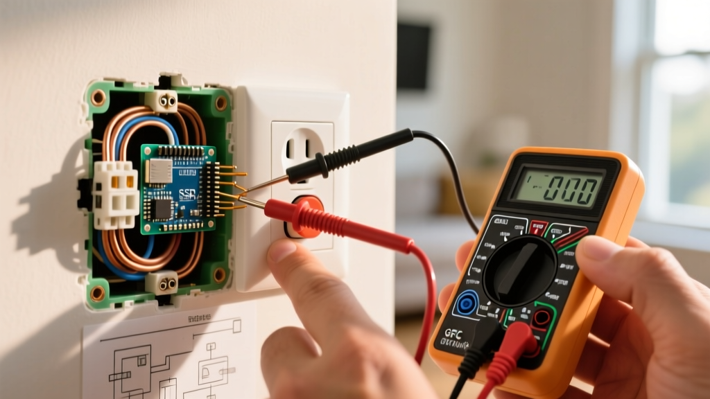
Even with meticulous installation, errors can occur. Before buttoning up the wall plate, test the circuit. If the breaker trips immediately or the receptacle fails a standard 3-light plug-in tester, consult this diagnostic matrix:
| Tester Indication | Probable Failure Mode | Corrective Action |
|---|---|---|
| Open Neutral | White wire disconnected or broken at the donor box. | Check the upstream neutral splice; ensure wire nut is tight and no copper is exposed outside the nut. |
| Reversed Polarity | Black and white wires swapped on terminal screws. | Verify black is on the brass screw (hot) and white is on the silver screw (neutral). |
| Open Ground | Bare copper not making contact with the metal box or green screw. | Ensure the ground pigtail is securely fastened to the receptacle's green screw and the box's ground clip. |
| Breaker Trips Instantly | Dead short (Hot touching Ground or Neutral). | Inspect the donor box for pinched wires or a ground wire accidentally touching a brass terminal screw. |
For additional workplace and residential safety protocols regarding electrical installations and lockout/tagout procedures, consult the Occupational Safety and Health Administration (OSHA) electrical safety resources.
Final Inspection and Energizing
Once terminations are verified and torqued, carefully fold the wires into the back of the Carlon box using a 'Z' fold method to prevent pinching the insulation against the metal yoke of the receptacle. Secure the device to the box using the provided 6-32 mounting screws, attach the faceplate, and restore power at the breaker. Verify functionality with a heavy load (like a 1500W space heater) for 5 minutes to ensure the connections remain cool to the touch, confirming a successful, code-compliant installation.