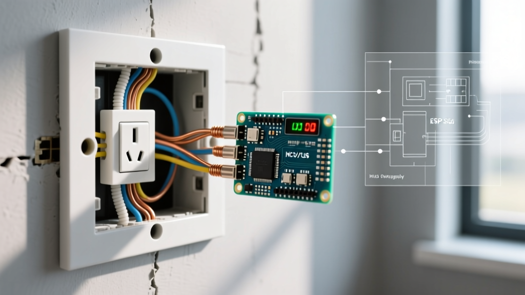

The Nomenclature Reality Check: 220V vs. 240V
Before diving into the inspection protocol, we must address a pervasive industry misnomer. When homeowners and junior technicians ask for a wiring diagram for 220 outlet configurations, they are almost universally referring to modern 240V split-phase circuits. The 220V standard was phased out in North America decades ago, yet the colloquialism persists. As an inspector or advanced DIYer, understanding this distinction is critical for selecting the correct testing equipment and referencing the accurate National Electrical Code (NEC) articles.
Modern residential 240V circuits utilize a center-tapped transformer to deliver two 120V legs (Hot 1 and Hot 2) that are 180 degrees out of phase. When measured across both legs, you get 240V. When measured from either leg to neutral or ground, you get 120V. This foundational physics dictates every testing procedure outlined in this guide.
⚠️ SAFETY WARNING: 240V circuits carry lethal amperage (typically 30A to 50A). Never perform live-terminal testing without Category III (CAT III) or Category IV (CAT IV) rated test leads and a True-RMS multimeter. Always verify your meter on a known live source before and after testing the target circuit.Decoding the Wiring Diagram for 220 Outlet Configurations
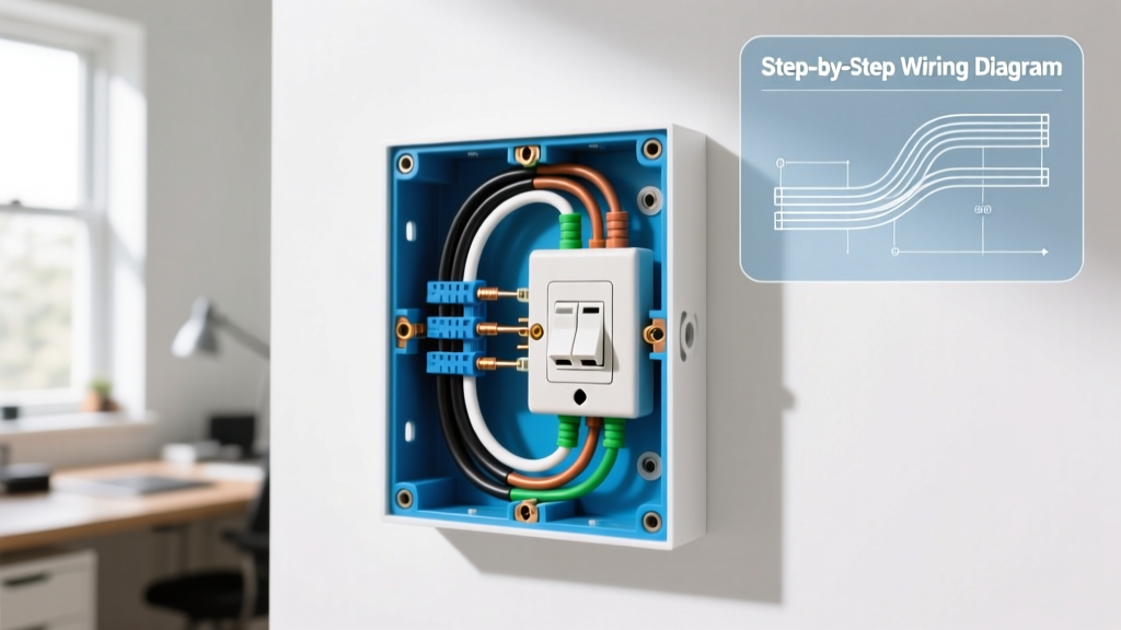
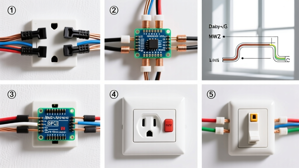
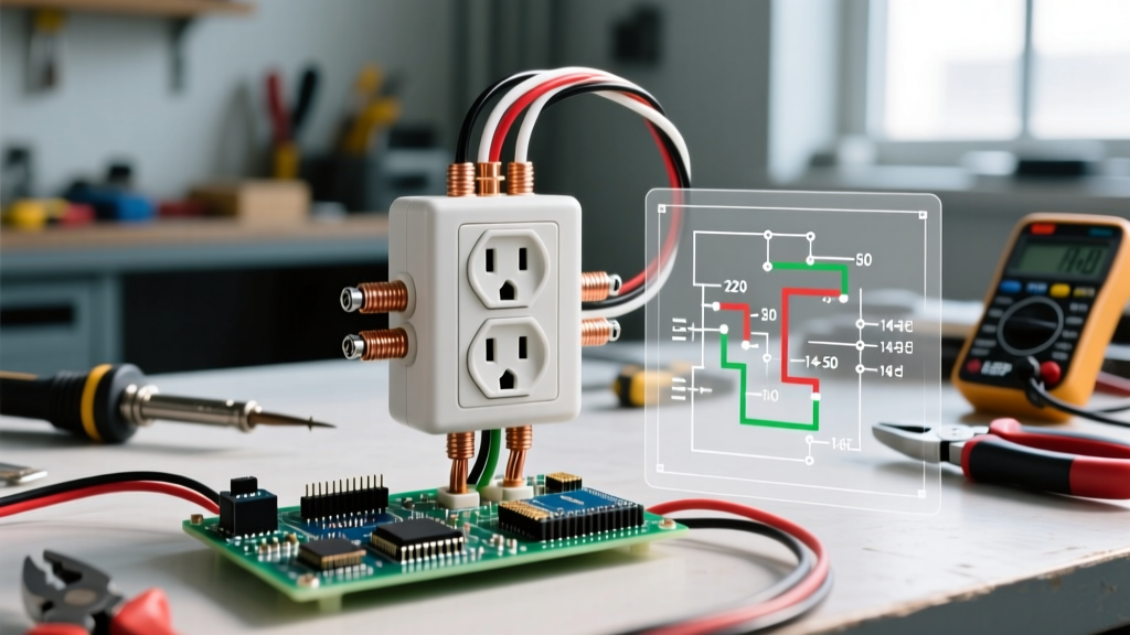
Inspectors primarily encounter two distinct 240V receptacle topologies in residential and light-commercial settings. Understanding the pinout and terminal designations on the wiring diagram is the first step in verifying correct installation.
1. NEMA 14-50 (4-Wire: 50 Amp)
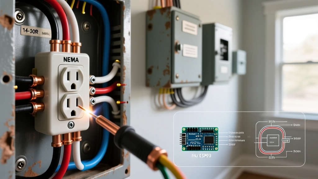
The NEMA 14-50 is the modern standard for electric ranges, heavy-duty air compressors, and Level 2 Electric Vehicle (EV) chargers. The wiring diagram for this 220 outlet variant features four terminals:
- X (Hot 1): Connects to the black wire (120V to ground).
- Y (Hot 2): Connects to the red wire (120V to ground, 180° out of phase with X).
- W (Neutral): Connects to the white wire. Required for appliances that utilize 120V for control boards, timers, or lights.
- G (Ground): Connects to the bare copper or green wire. The dedicated equipment grounding conductor (EGC).
2. NEMA 6-50 (3-Wire: 50 Amp)
Commonly found in welding shops and for specific 240V-only tools (like plasma cutters), the NEMA 6-50 lacks a neutral wire. The diagram only includes X, Y, and G terminals. Inspector Note: If you find a 4-wire cable (with a neutral) wired to a NEMA 6-50 receptacle, the neutral must be capped and isolated in the box; it cannot be terminated on the ground lug.
The 2026 Inspection & Testing Protocol
A proper inspection goes far beyond plugging in a tester. It requires a systematic approach encompassing mechanical verification, dead-front testing, and live-load analysis.
Phase 1: Visual and Mechanical Inspection
Before energizing the circuit, remove the receptacle cover and extract the device from the junction box. Inspect the following:
- Wire Gauge & Type: A 50A circuit mandates a minimum of 6 AWG copper (THHN/THWN) or 4 AWG aluminum. Verify the wire insulation is not nicked or degraded by heat.
- Receptacle Grade: For continuous loads like EV charging (which runs for 8+ hours at 80% capacity), the National Fire Protection Association (NFPA) and EV manufacturers strongly recommend industrial-grade receptacles like the Hubbell 9450A. Residential-grade models (e.g., Leviton 279-S00) are notorious for thermal runaway under continuous 40A EV loads.
- Torque Verification: Loose lugs cause arcing and fires. Use a calibrated torque screwdriver (such as the CDI 401SM). The Hubbell 9450A requires exactly 75 inch-pounds of torque on its terminal screws. If the installer did not use a torque tool, the connections must be re-terminated.
Phase 2: Live Voltage Testing Matrix
Using a CAT III True-RMS multimeter (e.g., Fluke 117), perform the following live-voltage tests at the receptacle slots. Reference the Fluke Multimeter Testing Best Practices for proper probe placement to avoid shorting adjacent slots.
| Test Point | Expected (NEMA 14-50) | Expected (NEMA 6-50) | Fault Indication & Diagnostics |
|---|---|---|---|
| Hot 1 to Hot 2 | 240V (±5%) | 240V (±5%) | Low voltage indicates utility drop, undersized feeder wire, or a loose busbar connection in the main panel. |
| Hot 1 to Ground | 120V | 120V | 0V indicates an open ground. 240V indicates a severe miswire (ground tied to opposite hot leg). |
| Hot 2 to Ground | 120V | 120V | Same as above. Verifies the integrity of the Equipment Grounding Conductor (EGC). |
| Hot 1 to Neutral | 120V | N/A | Fluctuating voltage indicates a loose neutral at the panel or receptacle. |
| Neutral to Ground | < 2V | N/A | Voltage > 2V under load indicates a shared neutral violation or undersized neutral conductor. |
Common Failure Modes & Code Violations
During field inspections, specific failure modes appear repeatedly when analyzing a wiring diagram for 220 outlet setups. Be on high alert for the following:
1. The "Bootleg" Ground on Legacy NEMA 10-30 Conversions
Older homes often feature NEMA 10-30 (3-prong, ungrounded) dryer outlets. A dangerous and illegal DIY fix involves installing a 4-prong NEMA 14-30 or 14-50 receptacle and jumping the neutral terminal to the ground terminal to "fake" a ground. This is a lethal violation. If the neutral wire ever disconnects, the chassis of the appliance becomes energized at 120V. Correction: The circuit must be rewired with a dedicated 4-wire cable, or a GFCI breaker must be installed with a "No Equipment Ground" label (per NEC 250.114).
2. Missing GFCI Protection (NEC 210.8(F))
One of the most significant code shifts in recent years is the requirement for Ground Fault Circuit Interrupter (GFCI) protection on 240V outlets. According to the Electrical Safety Foundation International (ESFI) and recent NEC updates, 240V receptacles rated 125V to 250V, single-phase, 150V or less to ground, and 50A or less (which includes NEMA 14-50 and 14-30 outlets in kitchens, laundry areas, and garages) must have GFCI protection. If you are inspecting a newly installed EV charger or range outlet in a garage and it is on a standard 2-pole breaker without GFCI, it is a code violation.
3. Thermal Runaway Under Continuous Load
EV chargers draw a continuous 40A load on a 50A circuit. Standard residential receptacles are only tested for intermittent loads. After 30 minutes of charging, a cheap receptacle's internal brass contacts can loosen due to thermal expansion and contraction, leading to arcing.
Testing Protocol: Run the 240V load for 30 minutes. Use an infrared thermometer (like the Fluke 62 MAX+) to scan the receptacle face and the breaker panel. If the receptacle face exceeds 140°F (60°C) or is more than 30°F hotter than ambient room temperature, the receptacle is failing and must be replaced with an industrial-grade, EV-rated model.
Final Inspection Sign-Off
Reading and executing tests based on a wiring diagram for 220 outlet circuits requires precision, the right diagnostic tools, and a firm grasp of modern electrical codes. By verifying torque specifications, validating true split-phase voltage, and ensuring compliance with modern GFCI mandates, you guarantee a safe, high-performance circuit capable of handling the demanding loads of modern appliances and electric vehicles.