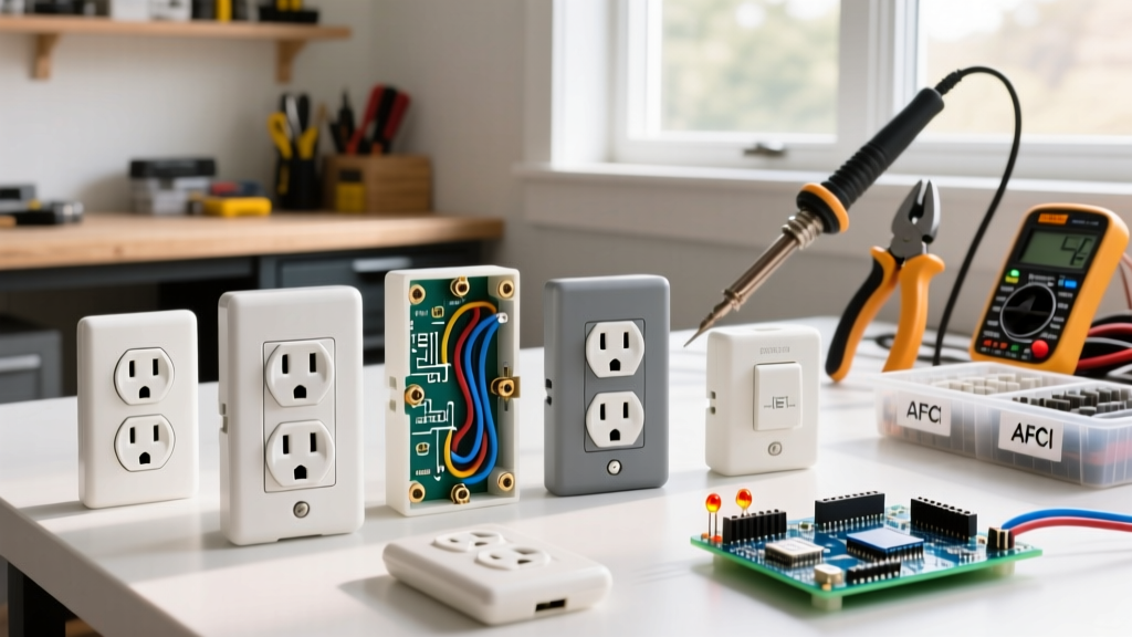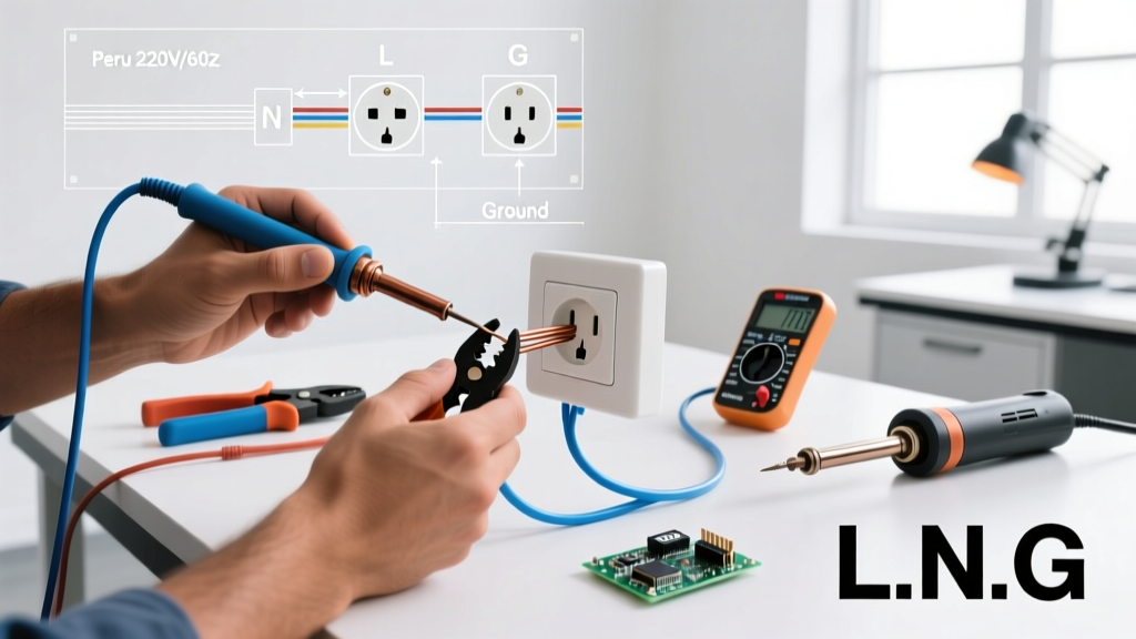

Why Routine Wall Electrical Outlet Inspection Matters
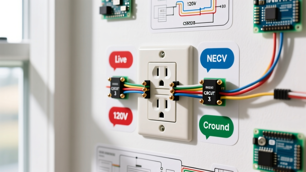
A standard 120V NEMA 5-15R wall electrical outlet is the most frequently used electrical interface in any residential or commercial building. Despite their ubiquity, these receptacles are subject to mechanical wear, thermal cycling, and potential wiring degradation. According to the National Fire Protection Association (NFPA), electrical distribution and lighting equipment are consistently among the top causes of home fire deaths and property damage. A loose internal connection, a compromised ground path, or degraded insulation can silently transition from a minor nuisance to a severe arc-fault hazard.
This comprehensive inspection and testing guide moves beyond basic visual checks. We will cover precise voltage tolerances defined by ANSI C84.1, mechanical tension testing, and advanced multimeter diagnostics to uncover hidden wiring faults like bootleg grounds and shared neutral overloads.
Essential Diagnostic Tools for Outlet Testing
Professional-grade diagnostics require more than a simple neon voltage tester. To properly evaluate a wall electrical outlet, assemble the following tools:
- Receptacle Tester (e.g., Klein Tools RT250): Priced around $35, this tool verifies basic wiring topology and includes a button to trip GFCI circuits. Avoid the $8 generic models; they lack the solenoid strength to reliably trip older GFCI breakers.
- True-RMS Digital Multimeter (e.g., Fluke 117): Retailing near $210, a True-RMS meter is critical for measuring non-linear loads accurately. As noted by Fluke Corporation, standard averaging meters can provide dangerously inaccurate readings on circuits with modern LED drivers or switching power supplies.
- Receptacle Tension Tester: A specialized tool (like the Hubbell RT1) used to measure the mechanical grip of the outlet's internal contacts on a plug blade.
- Non-Contact Voltage Tester (NCVT): For initial safety verification before removing the faceplate.
Step 1: The Visual and Physical Inspection
Before inserting any testing devices, perform a rigorous physical evaluation of the wall electrical outlet. Look for the following failure indicators:
Polycarbonate Degradation and Thermal Damage
Inspect the faceplate and the receptacle yoke for yellowing, brittleness, or soot marks. Discoloration around the hot (short) slot indicates historical arcing or chronic overloading. If the outlet feels warm to the touch under normal load conditions, it is an immediate red flag requiring circuit de-energization.
The Plug Retention (Tension) Test
Internal copper-alloy contacts lose their spring tension over years of plug insertion and removal. Insert a standard 3-prong plug into the top and bottom receptacles. If the plug slides in without resistance or falls out when lightly pulled, the outlet is mechanically failed. Loose connections increase electrical resistance, generating excessive heat (I²R losses) that can melt the housing and ignite surrounding dust or insulation.
Tamper-Resistant (TR) Shutter Verification
For any modern installation, verify the presence of TR shutters. Look inside the slots for the white or black plastic barriers. These mechanical shutters require simultaneous, equal pressure on both the hot and neutral blades to open, preventing children from inserting single conductive objects.
Step 2: Polarity and Wiring Verification
Insert your receptacle tester into the wall electrical outlet. The RT250 uses a combination of three LED indicators to map the wiring topology. Use the matrix below to interpret the results:
| Wiring Condition | Left Light (Yellow) | Center Light (Yellow) | Right Light (Red) | Action Required |
|---|---|---|---|---|
| Correct Wiring | OFF | ON | ON | None (Proceed to voltage test) |
| Open Ground | ON | ON | OFF | Check ground wire termination at panel/outlet |
| Open Neutral | OFF | OFF | ON | Inspect neutral bus bar and pigtail connections |
| Hot/Neutral Reversed | ON | OFF | ON | Swap brass and silver terminal wires immediately |
| Hot/Ground Reversed | ON | OFF | OFF | Dangerous; verify panel grounding and wire routing |
Step 3: Precision Multimeter Voltage & Ground Testing
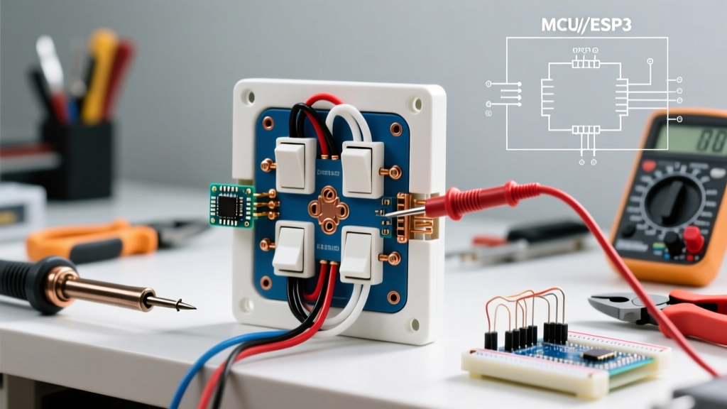
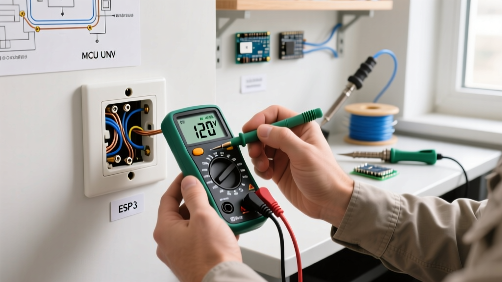
A receptacle tester only confirms topology; it does not measure voltage quality or ground impedance. Set your Fluke 117 to AC Voltage (V~) and perform the following three measurements on the wall electrical outlet:
1. Hot to Neutral (H-N)
Insert the red probe into the short (hot) slot and the black probe into the long (neutral) slot. According to the ANSI C84.1 standard, the acceptable voltage range for a 120V nominal system is between 114V and 126V. Readings consistently below 114V indicate voltage drop, often caused by undersized wiring, excessively long circuit runs, or an overloaded transformer.
2. Hot to Ground (H-G)
Move the black probe to the U-shaped ground slot. This reading should be nearly identical to your H-N reading (within 1V). A significant discrepancy here indicates a high-resistance ground path, which will prevent circuit breakers from tripping promptly during a ground fault.
3. Neutral to Ground (N-G)
Place the probes in the neutral and ground slots. This is the most revealing test. Under no-load conditions, N-G voltage should be 0.0V to 0.5V. Under a heavy load (e.g., running a 1500W space heater on the same circuit), the N-G voltage may rise to 1.5V or 2.0V due to the inherent resistance of the neutral wire. If your N-G voltage exceeds 2.0V under normal load, the circuit is likely overloaded, or the neutral wire is undersized/damaged.
Unmasking Hidden Hazards: Bootleg Grounds and Backstabbing
Two of the most dangerous conditions a wall electrical outlet can harbor will not always be caught by a basic 3-light tester.
The Bootleg Ground (False Ground)
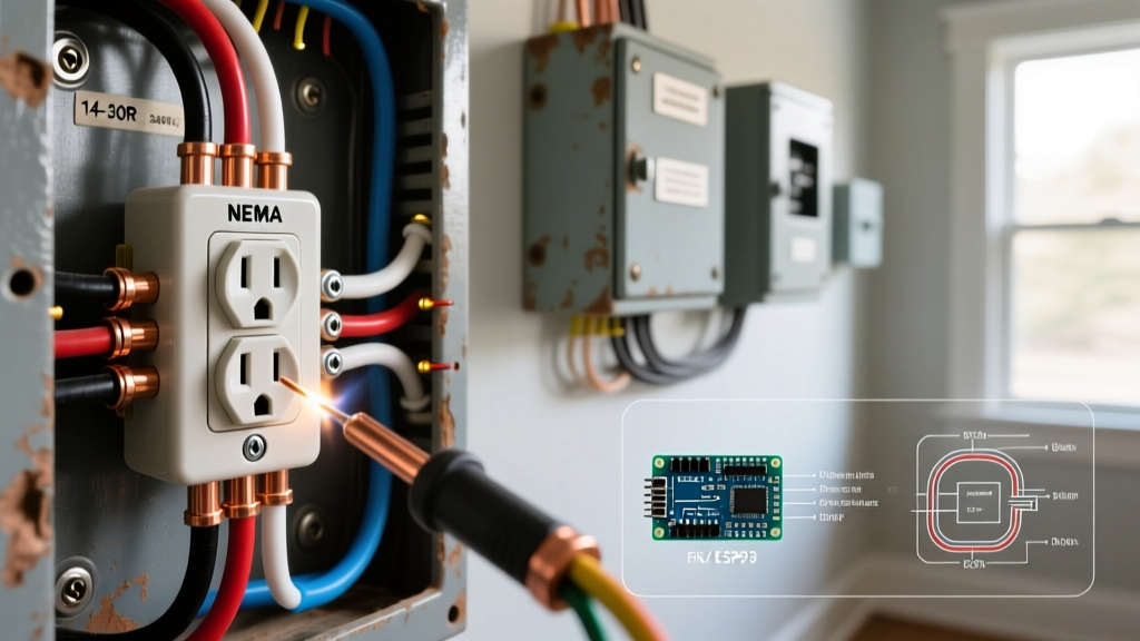
In older homes with ungrounded 2-wire systems, unethical handymen sometimes install a jumper wire between the neutral terminal and the ground screw on a 3-prong receptacle. This tricks a standard receptacle tester into showing "Correct Wiring." However, if the neutral wire ever breaks upstream, the metal chassis of any plugged-in appliance becomes energized at 120V. To test for a bootleg ground, you must remove the faceplate, pull the receptacle from the junction box, and visually verify that the bare/green ground wire originates from the main panel, not from the neutral terminal.
Backstabbed (Push-In) Connections
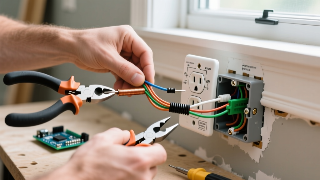
Many contractors use the quick-wire push-in holes on the back of 15A receptacles to save time. These connections rely on a small internal spring clip gripping a 14 AWG wire. Over years of thermal expansion and contraction, these clips loosen, creating a high-resistance arc fault hazard. The National Electrical Code (NEC) and best practices dictate that all wires should be stripped to exactly 3/4 inch and wrapped clockwise around the side terminal screws, tightened to the manufacturer's specified torque (typically 14 in-lbs for standard residential devices).
2026 NEC Compliance and Upgrade Triggers
When inspecting and testing outlets, keep current code requirements in mind. While you are not required to bring an entire existing home up to current code simply by replacing a broken receptacle, certain upgrades are highly recommended for safety:
- GFCI Expansion: Modern codes require Ground Fault Circuit Interrupter protection in virtually all areas where water is present, including kitchens, bathrooms, garages, outdoors, and within 6 feet of sinks. If your tester fails to trip the GFCI via the test button, immediate replacement is mandatory.
- AFCI Integration: Arc-Fault Circuit Interrupters are now required in most living spaces (bedrooms, living rooms, hallways). If an outlet exhibits intermittent tripping, it may be detecting a parallel or series arc fault in the branch wiring, not a faulty breaker.
Safety Warning: Never perform internal wiring inspections or terminal torque checks while the circuit is energized. Always turn off the breaker at the main panel and verify the absence of voltage using a Non-Contact Voltage Tester (NCVT) and a multimeter before touching any bare conductors. For comprehensive workplace safety standards, refer to guidelines published by OSHA.
Frequently Asked Questions
Why does my wall electrical outlet buzz or hum?
A buzzing sound typically indicates a loose wire connection arcing behind the faceplate, or a heavy inductive load (like a large vacuum motor) causing electromagnetic vibration in the outlet's internal contacts. Turn off the breaker immediately and inspect the terminal screws for tightness and signs of thermal melting.
Can I use a 15A receptacle on a 20A circuit?
Yes, the NEC allows 15A NEMA 5-15R receptacles to be installed on a 20A branch circuit, provided there is more than one receptacle on the circuit (a duplex outlet counts as two). However, the wiring feeding the outlet must be 12 AWG copper to handle the 20A breaker.
What causes a GFCI outlet to trip when nothing is plugged in?
If a GFCI wall electrical outlet trips with no load attached, it is usually detecting a ground fault downstream (if other outlets are wired to its LOAD terminals), or the internal sensing circuitry of the GFCI itself has failed due to age or a previous voltage surge. GFCI devices typically have a functional lifespan of 7 to 10 years.