
Understanding Electrical Outlet Types United States Homes Require
When upgrading or troubleshooting residential wiring, identifying the correct receptacle is only half the battle. The National Electrical Manufacturers Association (NEMA) standardizes the electrical outlet types United States electricians and DIYers encounter. From standard 15-amp duplex receptacles to heavy-duty 50-amp EV charger outlets, each configuration demands specific wire gauges, breaker sizes, and installation techniques.
This guide bypasses generic advice, providing exact measurements, torque specifications, and step-by-step installation protocols for the three most critical US outlet types in 2026.
Quick Reference: Common US NEMA Configurations
| NEMA Type | Amperage / Voltage | Wire Gauge Required | Primary Application |
|---|---|---|---|
| NEMA 5-15R | 15A / 125V | 14 AWG (or 12 AWG) | Standard lighting & appliance circuits |
| NEMA 5-20R | 20A / 125V | 12 AWG | Kitchen countertops, heavy window ACs |
| GFCI (5-15R/5-20R) | 15A/20A / 125V | 14/12 AWG | Bathrooms, outdoors, garages, kitchens |
| NEMA 14-50R | 50A / 125-250V | 6 AWG Copper | Electric ranges, RV hookups, Level 2 EV chargers |
Phase 1: Universal Safety & Preparation Protocol
CRITICAL SAFETY WARNING: Never rely solely on a breaker panel label. Always verify the absence of voltage at the receptacle using a non-contact voltage tester (NCVT) and a digital multimeter before touching any bare copper.
- Lockout/Tagout (LOTO): Switch off the corresponding circuit breaker. Apply a physical lock or heavy tape over the breaker to prevent accidental re-energization.
- Verify Dead Circuit: Insert a multimeter into the top and bottom slots (Hot to Neutral, Hot to Ground). Both must read 0.00V.
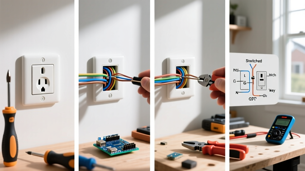
- Prepare Tools: You will need a Klein Tools 11063W wire stripper, a Phillips #2 screwdriver, a calibrated torque screwdriver (e.g., Milwaukee M12 or Wiha), and a bubble level.
Phase 2: Installing a Standard NEMA 5-15R (15-Amp Duplex)
The standard 15-amp receptacle is the backbone of US residential wiring. While seemingly simple, improper termination causes thousands of electrical fires annually due to arcing and thermal expansion.
Step-by-Step Termination
- Strip the Wires: Use the 14 AWG hole on your wire strippers to remove exactly 3/4 inch of insulation. Stripping too little exposes insulation to the clamp; stripping too much leaves bare copper exposed outside the terminal, creating a shock hazard.
- Form the J-Hook: Using needle-nose pliers, bend the bare copper into a tight 'J' shape. The loop must be perfectly round to ensure maximum surface contact under the screw head.
- Hook Direction: Place the loop around the brass (hot) and silver (neutral) terminal screws in a clockwise direction. This ensures that tightening the screw pulls the wire loop tighter rather than pushing it out.
- Grounding: Attach the bare/green ground wire to the green grounding screw. If the box is metal, you must also run a 6-inch ground pigtail from the box to the receptacle's ground screw.
- Apply Torque: According to NEC 110.14(D), terminals must be tightened to the manufacturer's specified torque. For standard Leviton or Eaton 15A receptacles, set your torque screwdriver to 14 in-lbs.
Expert Tip: Avoid "back-stabbing" (push-in) terminals found on the cheapest builder-grade receptacles. They rely on spring tension that degrades over time due to thermal cycling, leading to high-resistance connections. Always use the side-wire screw terminals or, if available, the screw-clamp "back-wiring" plates.
Phase 3: Wiring a GFCI Receptacle (Ground Fault Circuit Interrupter)
The U.S. Consumer Product Safety Commission (CPSC) mandates GFCI protection in all wet or damp locations. Wiring a GFCI incorrectly will either leave downstream outlets unprotected or cause the GFCI to trip continuously.
Identifying LINE vs. LOAD
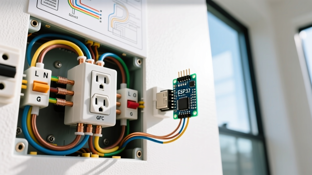
This is where 90% of DIY errors occur. A GFCI has two sets of terminals:
- LINE: Connects to the incoming power from the breaker panel.
- LOAD: Connects to downstream outlets that you want the GFCI to protect.
Installation Steps
- Identify the Line Cable: If multiple cables enter the box, temporarily separate them, turn the breaker on, and safely test with a multimeter to find the hot incoming cable. Turn the breaker back off.
- Terminate LINE Wires: Connect the incoming black (hot) to the brass LINE screw, and the incoming white (neutral) to the silver LINE screw. Torque to 14 in-lbs.
- Terminate LOAD Wires (If applicable): Connect the downstream black and white wires to the LOAD screws. If you are only protecting this single location, cap the LOAD wires with wire nuts and do not use these terminals.
- Grounding: Connect all ground wires together with a wire nut and a 6-inch pigtail to the green ground screw on the GFCI.
- Test the Circuit: Restore power. Press the "TEST" button on the receptacle face. It should click and cut power. Press "RESET" to restore. Use a plug-in GFCI tester to verify proper wiring at the outlet and any downstream LOAD outlets.
Phase 4: Installing a 240V NEMA 14-50R (EV Charger / Range)
With the explosion of Level 2 home EV charging in 2026, the NEMA 14-50R has become a highly requested upgrade. This is a 4-wire, 50-amp, 125/250V receptacle. Mistakes here can result in catastrophic equipment failure or fatal shock.
Wire Sizing and Breaker Selection
You must use a 50-amp double-pole breaker. The wire must be 6 AWG copper THHN/THWN (or 4 AWG aluminum). Do not use Romex/NM-B cable for runs inside walls unless it is specifically rated 6/3 NM-B, and even then, many local inspectors now require THHN in conduit for 50A continuous EV loads due to heat dissipation concerns.
Heavy-Duty Termination Steps
- Prepare the Conduit and Box: A NEMA 14-50 requires a deep, extra-capacity single-gang or double-gang mud ring box to accommodate the thick 6 AWG wires and the bulky receptacle body.
- Strip the 6 AWG Wire: Strip exactly 7/8 inch of insulation from the two hot wires (Black and Red), the neutral (White), and the ground (Green/Bare).
- Terminate the Hots (X and Y): Connect the Black and Red wires to the two brass terminal screws. These are the 120V legs that combine for 240V. Phase sequence does not matter for standard ranges or EV chargers.
- Terminate Neutral and Ground: Connect the White wire to the silver neutral screw (usually the center terminal). Connect the Ground wire to the green grounding screw.
- High-Torque Application: 6 AWG wire requires significant clamping force to prevent arcing under a 40A continuous EV load. Set your torque screwdriver to 45 to 50 in-lbs (check the specific receptacle datasheet, such as the Hubbell 9450A or Bryant 9450FR).
- Orientation: For EV chargers, many manufacturers (like Tesla) recommend installing the 14-50R with the ground pin facing UP to prevent strain on the heavy EV plug cable and to align with the cord's natural bend radius. Check your specific EVSE manual.
NEC Compliance & Final Inspection Checklist
Adhering to the National Electrical Code (NFPA 70) is non-negotiable for safety and insurance purposes. Before closing up your wall boxes, verify the following:
- AFCI/GFCI Dual Protection: In living spaces and kitchens, ensure your breakers or receptacles meet the latest dual-function AFCI/GFCI requirements mandated by recent NEC cycles.
- Box Fill Capacity: Ensure the electrical box has enough cubic inch volume for the number of wires, clamps, and the specific yoke of the receptacle installed. GFCIs and smart outlets require deeper boxes (minimum 22 cubic inches recommended).
- Receptacle Faceplate Fit: Use a bubble level to ensure the receptacle yoke is perfectly plumb before tightening the mounting screws. A crooked yoke will crack standard nylon faceplates when tightened.
By understanding the specific mechanical and electrical demands of these electrical outlet types United States buildings utilize, you ensure a safe, code-compliant, and durable installation that will withstand decades of thermal cycling and mechanical use.