
When troubleshooting residential lighting circuits, few configurations cause as much confusion as two way electrical light switch wiring. Before diving into the testing procedures, we must address a critical terminological divide: what the UK, Australia, and IEC standards refer to as a "two-way switch" is classified as a "3-way switch" under the North American National Electrical Code (NEC). Both terms describe the exact same electrical component: a Single Pole, Double Throw (SPDT) switch that allows a single light fixture to be controlled from two separate locations.
Whether you are diagnosing a flickering hallway light, verifying a new rough-in, or preparing to upgrade to smart relays, a systematic inspection and testing protocol is mandatory. This guide provides a professional-grade framework for inspecting and testing SPDT circuits, leveraging modern digital multimeters and strict adherence to the 2026 NEC safety standards.
⚠️ CRITICAL SAFETY WARNING: Never perform live voltage testing without proper Personal Protective Equipment (PPE) and a verified CAT III or CAT IV rated multimeter. Always follow OSHA electrical safety guidelines and Lockout/Tagout (LOTO) procedures before opening any junction box or removing switch faceplates.
Essential Diagnostic Tools for 2026
Accurate troubleshooting requires precision instruments. Relying on cheap, uncalibrated testers leads to false positives, especially with phantom voltages common in multi-way switch loops.
- Non-Contact Voltage Tester (NCVT): Klein Tools NCVT-3 (~$35). Features dual-range sensitivity (12-1000V AC) to detect both line voltage and low-voltage smart switch signals.
- Digital Multimeter (DMM): Fluke 117 True-RMS (~$210) or AstroAI DM6000AR (~$65). True-RMS is essential for accurately reading circuits that may have dimmer-induced harmonic distortion.
- Torque Screwdriver: Klein Tools 32550 (~$120). Calibrated to 12-14 in-lbs for standard residential switch terminal screws.
Phase 1: Visual & Mechanical Inspection (De-Energized)
Before restoring power, conduct a rigorous physical inspection of both switch boxes. Over 60% of multi-way switch failures stem from poor mechanical terminations rather than faulty switch internals.
Wire Gauge and Insulation Verification
Verify the traveler wires and common wires match the circuit breaker rating. A 15-amp breaker requires a minimum of 14 AWG copper; a 20-amp breaker mandates 12 AWG. Inspect the wire insulation at the terminal entry points. If the copper is scored or nicked from excessive stripping, the wire will act as a localized resistor, generating heat and eventually failing under load.
The Backstab vs. Screw Terminal Debate
Inspect how the wires are terminated. Many commercial-grade SPDT switches feature push-in (backstab) connectors. While UL-listed, backstab connections rely on a single spring-metal grip. On traveler wires, which carry current in alternating states, thermal cycling causes the spring to lose tension over 5 to 10 years, leading to arcing. Actionable fix: If you find backstabs, remove them, strip back to clean copper, and terminate under the side screw terminals, torquing to the manufacturer's specification (typically 12 in-lbs for 14 AWG, 14 in-lbs for 12 AWG).
Phase 2: Live Voltage Testing Protocol
Once the visual inspection is complete and the switches are reassembled, restore power at the breaker. Use your True-RMS DMM to map the voltage states. You will need to identify the Common terminal (usually a dark-colored screw) and the two Traveler terminals (usually brass-colored screws) on both Switch A (Line side) and Switch B (Load side).
Mapping the Voltage Matrix
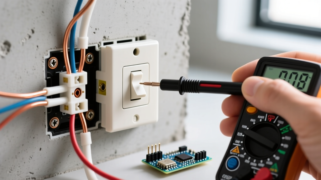
Set your DMM to AC Voltage. Place the black probe on a known ground (bare copper or metal box) and use the red probe to test the terminals. Below is the definitive voltage matrix for a properly functioning two way electrical light switch wiring setup.
| Switch A (Line) | Switch B (Load) | Switch A Common | Switch A Travelers | Switch B Common | Switch B Travelers | Light State |
|---|---|---|---|---|---|---|
| Toggle UP | Toggle UP | 120V | 120V on T1 / 0V on T2 | 120V | 120V on T1 / 0V on T2 | ON |
| Toggle DOWN | Toggle UP | 120V | 0V on T1 / 120V on T2 | 0V | 120V on T1 / 0V on T2 | OFF |
| Toggle UP | Toggle DOWN | 120V | 120V on T1 / 0V on T2 | 0V | 120V on T1 / 0V on T2 | OFF |
| Toggle DOWN | Toggle DOWN | 120V | 0V on T1 / 120V on T2 | 120V | 0V on T1 / 120V on T2 | ON |
Note: T1 and T2 represent the two traveler wires. If your readings show ~40V to 60V on a traveler that should read 0V, you are experiencing phantom voltage induced by capacitive coupling from the adjacent live traveler wire. A DMM with a low-impedance (LoZ) mode, like the Fluke 117, will bleed off this ghost voltage and read a true 0V.
Phase 3: Dead Continuity Testing (Ring-Out)
If the live voltage test reveals missing power at the travelers or the load common, you must isolate the wiring. Turn off the breaker, verify zero voltage, and disconnect all wires from both switches.
- Test the Travelers: Set your DMM to Continuity (the diode/audio symbol). Place one probe on Traveler 1 at Switch A, and the other on Traveler 1 at Switch B. You should hear a continuous beep (resistance < 1 ohm). Repeat for Traveler 2. If a traveler shows infinite resistance (OL), the wire is broken inside the wall or disconnected in an intermediate junction box.
- Test the Switch Internals: With the switch completely isolated, place probes on the Common terminal and Traveler 1. Toggle the switch. The DMM should beep in one position and read 'OL' in the other. Move the probe to Traveler 2 and toggle again. The states should invert. If the switch shows continuity to both travelers simultaneously, or neither, the internal brass wiper is burned out. Replace the SPDT switch.
Common Failure Modes & Edge Cases
Even seasoned electricians encounter bizarre behaviors in multi-way circuits. Here are the most complex edge cases you will face when inspecting two way electrical light switch wiring:
1. The Shared Neutral Violation (NEC 300.3(B))
In older homes, it was common practice to borrow a neutral wire from a completely different circuit to complete the light fixture's return path. The 2023 and 2026 NEC cycles strictly enforce that all current-carrying conductors (line, travelers, load, and neutral) must be routed within the same cable or conduit to prevent electromagnetic induction and overheating. If your NCVT detects a strong magnetic field around the cable sheath, or if a GFCI breaker trips randomly when the two-way switch is toggled, you likely have a neutral mismatch.
2. Smart Switch Upgrade Incompatibility
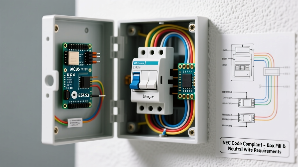
Upgrading a traditional two-way setup to a smart system (like Lutron Caséta or Leviton Decora Smart) fundamentally changes the wiring requirements. Traditional SPDT circuits often do not have a neutral wire present in the switch boxes—only at the light fixture. If you are inspecting a box to prepare for a smart switch installation, you must verify the presence of a bundled white neutral wire. If absent, you must either pull a new 14/3 or 12/3 cable from the fixture, or utilize a no-neutral smart switch system that relies on a bypass resistor installed at the light canopy.
3. Miswired Traveler-to-Common
A classic DIY error is connecting the line/load wire to a brass traveler terminal, and a traveler wire to the dark common terminal. The circuit will appear to work partially, but the light may stay on dimly when off, or the switches will only function if the other switch is held in a specific position. Always verify terminal mapping using the continuity ring-out method before energizing.
Final Compliance and Documentation
Proper inspection of two way electrical light switch wiring goes beyond just making the light turn on. It requires verifying that the grounding path is continuous, that terminal torques meet manufacturer specifications to prevent arc faults, and that the circuit complies with NFPA 70 (National Electrical Code) standards regarding conductor routing and box fill capacities.
For further reading on safe multimeter usage and advanced circuit diagnostics, consult the Fluke Electrical Testing Knowledge Base. By adhering to this structured testing matrix, you ensure the longevity, safety, and reliability of your residential lighting circuits.