
Why Inspecting Electrical Outlet Plug Types Matters
When diagnosing circuit failures, verifying the integrity of electrical outlet plug types is the first line of defense against arc faults, equipment damage, and electrical fires. While a standard $10 plug-in tester might illuminate the 'correct' lights, it fails to detect high-resistance connections, degraded contact tension, or dangerous 'bootleg' grounds. As residential electrical loads increase—driven by high-wattage appliance circuits and Level 2 EV chargers—relying on superficial testing is no longer sufficient. This guide details the professional inspection protocols required to validate NEMA configurations, ensure NEC compliance, and uncover hidden failure modes in both 120V and 240V receptacles.
Decoding the NEMA Configuration Matrix
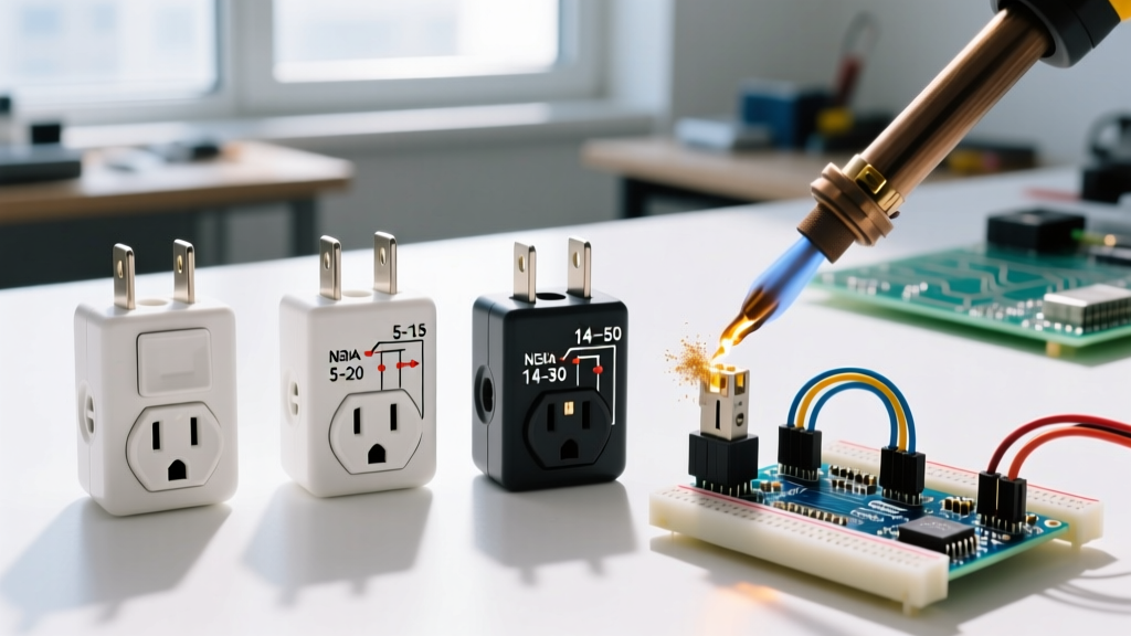
North American electrical outlet plug types are governed by the National Electrical Manufacturers Association (NEMA). Understanding the specific amperage, voltage, and wire gauge requirements for each configuration is critical before applying any test equipment.
| NEMA Config | Voltage | Amps | Min. Wire Gauge | Common Application |
|---|---|---|---|---|
| 1-15R | 125V | 15A | 14 AWG (Legacy) | Older homes, ungrounded 2-prong |
| 5-15R | 125V | 15A | 14 AWG | Standard residential 3-prong |
| 5-20R | 125V | 20A | 12 AWG | Kitchens, bathrooms, heavy tools |
| 6-20R | 250V | 20A | 12 AWG | Window AC units, commercial gear |
| 14-50R | 125/250V | 50A | 6 AWG (or 4 AWG) | EV chargers, electric ranges, RVs |
| L14-30R | 125/250V | 30A | 10 AWG | Transfer switches, portable generators |
The Professional Testing Arsenal
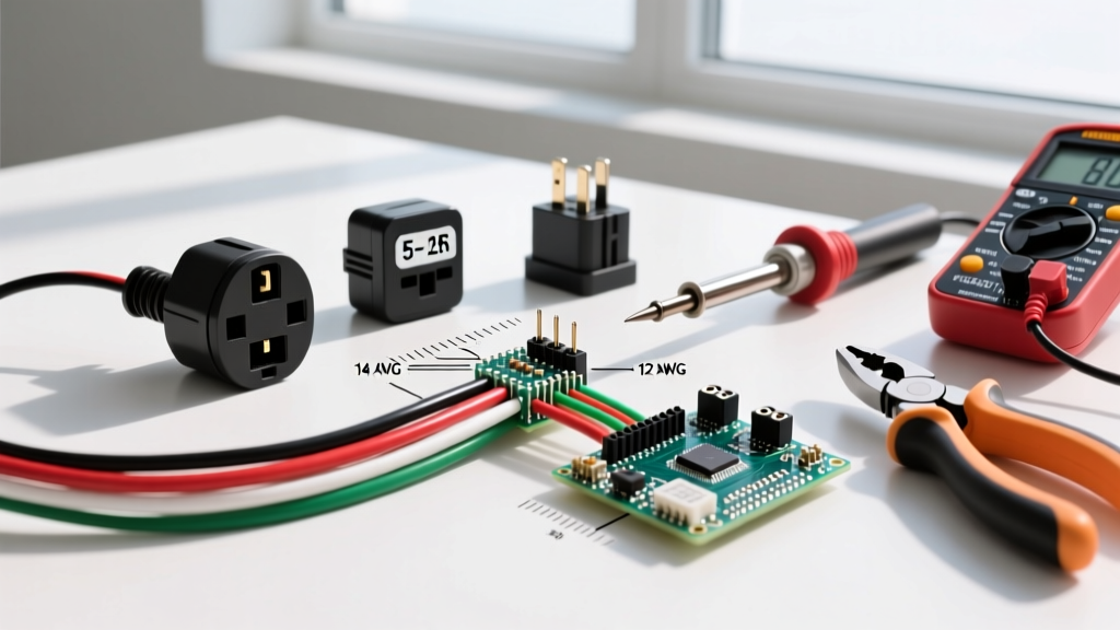
Accurate diagnosis requires moving beyond basic solenoid testers. A comprehensive inspection of electrical outlet plug types demands the following tools:
- Advanced GFCI Receptacle Tester: The Klein Tools RT250 (approx. $35) features an LCD screen that detects wiring faults and measures precise trip times for GFCI circuits, rather than relying on ambiguous LED codes.
- Digital Multimeter (DMM) with LoZ: A True-RMS meter like the Fluke T6-1000 (approx. $220) allows for non-contact voltage detection and Low Impedance (LoZ) testing to eliminate ghost voltages.
- Thermal Imaging Camera: The FLIR C5 (approx. $450) is essential for identifying micro-arcing and high-resistance connections under load that are invisible to the naked eye.
- Calibrated Torque Screwdriver: NEC 2023 and continuing into 2026 mandates torque verification for many terminations. A CDI 401SM ensures lugs are tightened to the manufacturer's exact inch-pound specifications.
Step-by-Step Inspection Protocol for 120V Receptacles
1. Visual and Physical Tension Testing
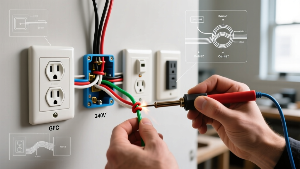
Before applying power, de-energize the circuit and remove the receptacle from the junction box. Inspect for 'backstabbed' push-in wire connectors. These spring-loaded contacts are notorious for loosening over time due to thermal cycling, leading to localized heating. Actionable fix: Migrate all backstabbed wires to the side-screw terminals or use UL-listed push-in connectors rated for 12 AWG solid wire.
Next, perform a tension test. Insert a standard NEMA 5-15P plug into the receptacle. If the plug slides in with minimal resistance or falls out under its own weight, the internal brass wipers have lost their spring temper. According to the U.S. Consumer Product Safety Commission (CPSC), loose receptacle contacts are a leading cause of residential arc faults. Replace any receptacle that fails the physical tug test.
2. Electronic Verification and Voltage Drop
Restore power and use your DMM to measure voltage. A healthy 120V circuit should read between 114V and 126V (a +/- 5% tolerance). Measure across the following points:
- Hot to Neutral (Short Slot to Long Slot): Should read ~120V.
- Hot to Ground (Short Slot to U-Ground): Should read ~120V.
- Neutral to Ground (Long Slot to U-Ground): Should read less than 2V. A reading higher than 2V indicates a loose neutral connection upstream or an overloaded shared neutral on a multi-wire branch circuit (MWBC).
Catching the 'Bootleg Ground' Illusion
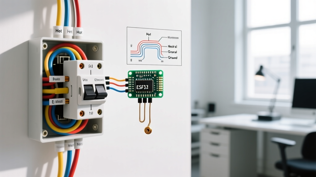
Warning: A standard plug-in tester will show 'Correct Wiring' on a receptacle where the ground screw has been illegally jumpered to the neutral terminal. This is known as a bootleg ground and poses a severe shock hazard if the neutral wire disconnects upstream.
To definitively rule out a bootleg ground when inspecting older electrical outlet plug types, use your multimeter's LoZ (Low Impedance) function or measure the voltage drop. Alternatively, turn off the circuit breaker. If the ground slot still shows continuity to the neutral slot with the power off and no load on the circuit, you have found a bootleg ground. The only code-compliant fix is to run a new equipment grounding conductor back to the panel or replace the receptacle with a GFCI, marking it 'No Equipment Ground' per NFPA 70 (NEC) Article 406.4(D).
High-Power 240V Testing: NEMA 14-50 and EV Chargers
With the surge in residential EV adoption, the NEMA 14-50R has become one of the most critical and frequently misinstalled electrical outlet plug types. A 14-50R provides two 120V legs, a neutral, and a ground, delivering 240V across the two hot legs for 50A continuous loads.
The Thermal Meltdown Failure Mode
Many DIYers and even some electricians wire NEMA 14-50 receptacles using the push-in lugs or fail to torque the screw terminals correctly. When an EV charger pulls a continuous 40A load for 8 hours, a loose connection will generate massive heat, melting the receptacle face and causing a fire. Inspection mandate: Always remove the 14-50R cover and verify that the wire insulation is not pinched under the terminal plates and that the terminals are torqued to the manufacturer's specification (typically 35 to 45 in-lbs for 6 AWG copper).
Testing Phase-to-Phase Voltage
Using a CAT III or CAT IV rated multimeter, test the two hot slots (the angled blades). You should read exactly 240V (+/- 5%). If you read 120V between the two hot slots, the breaker is incorrectly installed on a single phase leg rather than spanning two adjacent breaker spaces on opposite bus bars. Furthermore, test Hot A to Neutral (120V) and Hot B to Neutral (120V). If the EV charger utilizes the neutral pin for 120V internal logic, an open neutral will fry the charger's control board.
Troubleshooting Matrix: Tester Lights vs. Reality
While advanced LCD testers are preferred, many electricians still carry standard 3-light solenoid testers. Use this matrix to interpret ambiguous readings when inspecting electrical outlet plug types:
| Tester Indication | Likely Fault | Advanced Verification Step |
|---|---|---|
| Hot/Neutral Reversed | Polarity swapped at receptacle or panel | Verify slot lengths; ensure black wire is on brass screw, white on silver. |
| Open Ground | Missing ground wire or broken pigtail | Check for metallic conduit acting as ground path; measure Hot-to-Box voltage. |
| Hot/Ground Reversed | Ground wire accidentally landed on hot terminal | DANGER: Receptacle face may be energized. Verify with non-contact voltage tester. |
| All Lights Off | Open Hot or tripped GFCI upstream | Check upstream GFCI receptacles; verify breaker status and voltage at panel. |
Locking Plugs and Generator Receptacles (L14-30)
For portable generators and transfer switches, the NEMA L14-30R (30A, 125/250V, locking) is the standard. The twisting locking mechanism prevents accidental disconnects under load. When inspecting these, check the internal ceramic or high-temp thermoset housing for hairline cracks caused by dropping the heavy generator plug onto the ground. Also, inspect the ground pin for bending or scoring, which can prevent the plug from fully seating and locking, leading to phase-loss under heavy starting loads.
Safety and Compliance Standards
Inspecting and testing electrical systems carries inherent risks. Always adhere to lockout/tagout (LOTO) procedures when opening junction boxes. The Occupational Safety and Health Administration (OSHA) strictly mandates the use of appropriately rated PPE and CAT-rated testing equipment when working on energized circuits. Furthermore, any modifications or replacements of electrical outlet plug types must comply with the latest edition of the National Electrical Code, particularly regarding AFCI and GFCI protection requirements in finished basements, kitchens, and outdoor areas.
By combining physical tension testing, advanced multimeter diagnostics, and thermal imaging, you can ensure that every receptacle in a facility is not only wired correctly but capable of handling its designated load safely for years to come.