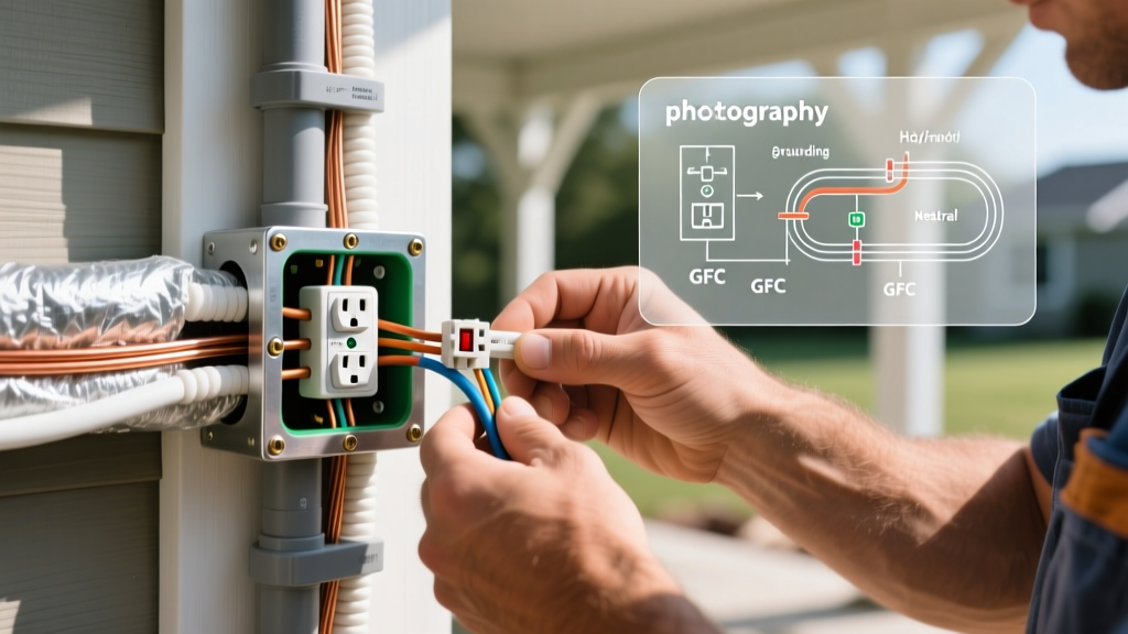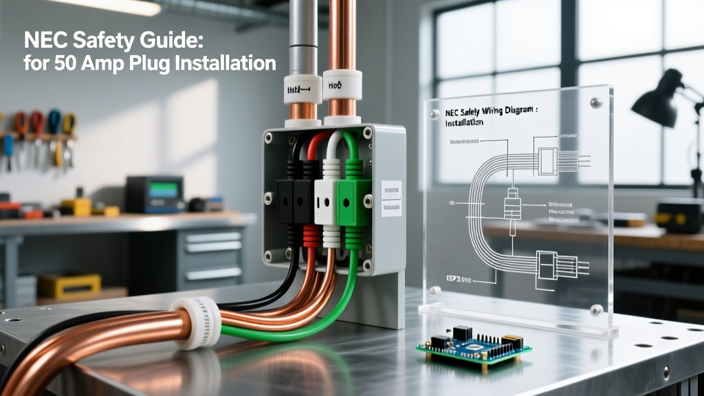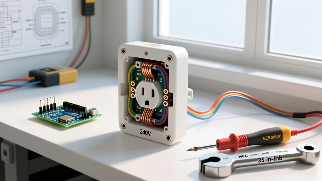

The Critical Nature of 240V Receptacle Inspection
Testing a 240 electrical outlet requires a fundamentally different approach than verifying a standard 120V wall receptacle. With double the voltage and significantly higher fault current potential, 240V circuits—commonly used for electric vehicle (EV) chargers, welders, and heavy appliances—operate near the upper limits of residential electrical systems. A loose connection or degraded terminal on a 50-amp circuit can generate enough heat to melt thermoset plastics and ignite structural fires long before a standard breaker trips.
As we move through 2026, the continuous duty cycles demanded by modern Level 2 EV chargers and smart home appliances have exposed latent flaws in older receptacle installations. This inspection and testing guide provides a rigorous, professional-grade methodology for diagnosing, verifying, and troubleshooting 240V outlets, ensuring compliance with the latest safety standards.
Safety Warning: Never bypass arc flash safety protocols. According to OSHA Electrical Safety Standards, working on or testing exposed 240V terminals requires appropriate Personal Protective Equipment (PPE), including CAT III/IV rated gloves and safety glasses. Always verify your testing equipment on a known live proving unit before and after testing the target circuit.
Essential Diagnostic Tools for High-Voltage Testing
Standard hardware store voltage testers are insufficient for diagnosing high-amperage 240V circuits under load. You must utilize precision instruments capable of handling transient voltage spikes.
- True-RMS Digital Multimeter (DMM): A CAT III 1000V or CAT IV 600V rated meter is mandatory. The Fluke 87V Industrial True-RMS (approx. $450) remains the industry benchmark for its low-impedance (LoZ) mode, which eliminates ghost voltage readings. For budget-conscious inspectors, the Klein Tools MM600 (approx. $55) offers reliable CAT III protection.
- Non-Contact Voltage Tester (NCVT): A dual-range NCVT like the Klein NCVT-3 is critical for initial dead-front verification without exposing live busbars.
- Calibrated Torque Screwdriver: To verify terminal tightness per NEC 110.14(D), an insulated torque driver such as the Wiha 320P with a 10-75 in-lb range is required.
- Thermal Imaging Camera: A tool like the FLIR ONE Edge Pro allows you to detect resistive heating at the receptacle yoke and breaker terminals under load.
Phase 1: Visual and Mechanical Inspection
Receptacle Selection and Thermal Degradation
Before introducing a multimeter to the circuit, de-energize the breaker and perform a tactile and visual inspection of the receptacle face and yoke. Look for micro-fractures in the phenolic or nylon faceplate, which indicate past thermal runaway events.
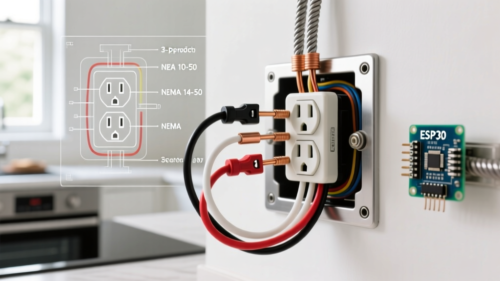
The EV Charger Receptacle Controversy: If you are inspecting a NEMA 14-50 outlet used for EV charging, identify the manufacturer immediately. The Leviton 279-S00 has been widely documented by electrical engineers and the EV community as prone to thermal degradation under continuous 40A loads due to its internal wiper-contact design. In contrast, the Hubbell 9450A utilizes heavy-duty brass screw terminals and is the gold standard for continuous-duty 240V applications. If a Leviton 279-S00 is found on an EV circuit, immediate replacement with a Hubbell or Bryant equivalent is highly recommended.
Phase 2: Live Voltage Testing Protocol
Once the visual inspection is complete and the cover plate is safely removed to expose the terminal screws, restore power at the panel. Follow this strict sequence to map the circuit's electrical characteristics.
- Prove the Tester: Insert the DMM probes into a known live 120V receptacle to confirm the meter and leads are functioning.
- Line-to-Line (L1 to L2): Place one probe on the brass terminal of the X-slot (L1) and the other on the brass terminal of the Y-slot (L2). Expected Reading: 240V (±5%). A reading below 228V indicates excessive voltage drop, likely due to undersized wire runs or a failing utility transformer tap.
- Line-to-Ground (L1 to G & L2 to G): Measure from L1 to the green grounding terminal, then L2 to ground. Expected Reading: 120V for each. This confirms the ground path is intact and bonded correctly at the main service panel.
- Line-to-Neutral (L1 to N & L2 to N): For 4-wire configurations (like NEMA 14-30 or 14-50), measure from each hot leg to the silver neutral terminal. Expected Reading: 120V. This verifies the 120V control circuits in appliances (like dryer timers or EV charger logic boards) will receive proper voltage.
- Neutral-to-Ground (N to G): Measure between the neutral and ground terminals. Expected Reading: Less than 2.0V. A reading higher than 2V indicates a loose neutral connection at the panel, a shared neutral violation, or an improperly bonded subpanel. This is a critical failure mode that can fry 120V appliance logic boards.
NEMA Receptacle Testing Matrix
Understanding the specific NEMA configuration is vital for proper inspection. Below is a diagnostic matrix for the most common 240V residential and commercial outlets.
| NEMA Config | Amperage | Wires | Common Application | L1-L2 Target | N-G Target |
|---|---|---|---|---|---|
| 6-20R | 20A | 3 (Hot, Hot, Ground) | Window ACs, Small Compressors | 240V | N/A |
| 10-30R | 30A | 3 (Hot, Hot, Neutral*) | Pre-1996 Electric Dryers | 240V | N/A (Unsafe) |
| 14-30R | 30A | 4 (Hot, Hot, Neutral, Ground) | Modern Electric Dryers | 240V | < 2.0V |
| 14-50R | 50A | 4 (Hot, Hot, Neutral, Ground) | EV Chargers, RV Hookups, Ranges | 240V | < 2.0V |
*Note: NEMA 10-30 configurations rely on the neutral as a combined ground/neutral path, a practice banned by the NEC for new installations since 1996 due to shock hazards if the neutral wire breaks.
Phase 3: Torque Verification and NEC Compliance
Voltage testing only tells half the story. A receptacle can show perfect 240V at no-load, but fail catastrophically when a 40A EV charger draws continuous current. The NFPA 70 National Electrical Code (NEC) strictly mandates the use of calibrated torque tools for terminal connections.
During an inspection, power down the circuit and verify the terminal screw torque. For the industry-standard Hubbell 9450A 14-50R receptacle, the manufacturer specifies 75 in-lbs for the line and neutral terminals, and 35 in-lbs for the ground terminal. Hand-tightening with a standard screwdriver typically yields only 15-25 in-lbs, leading to microscopic arcing, oxidation, and eventual thermal failure. If the wires show signs of heat discoloration (darkened copper) or the insulation is melted back more than 1/2 inch, the conductor must be cut back to clean copper and re-terminated.
Advanced Troubleshooting: Edge Cases and Failure Modes
When standard voltage tests pass but the connected appliance still malfunctions or the breaker trips intermittently, investigate these advanced failure modes:
- The Floating Neutral in RV/EV Setups: If a NEMA 14-50 outlet has a broken or high-resistance neutral wire upstream, the 120V legs become unbalanced under load. A 120V RV appliance might suddenly receive 180V, destroying its power supply. Always perform a load-test using a plug-in resistive load bank while monitoring the N-G voltage; if it spikes above 3V under load, the neutral path is compromised.
- Backstabbed or Push-In Terminals: While rare on 240V receptacles, some cheaper 20A (NEMA 6-20) outlets allow push-in wiring. These internal spring clips lose tension over time, especially under thermal cycling. Any 240V outlet utilizing push-in connections must be flagged for immediate replacement with screw-terminal equivalents.
- Shared Neutral Violations (MWBC Errors): In some older workshops, a 240V circuit might have been improperly derived from a Multi-Wire Branch Circuit (MWBC) without a simultaneous disconnect breaker. According to U.S. Department of Energy EV Charging Guidelines and NEC 210.4, this poses a severe shock hazard to anyone servicing the outlet. Verify that both hot legs are tied to a common internal trip or handle-tied breakers in the panel.
Summary
Inspecting a 240 electrical outlet goes far beyond confirming that a tool powers on. By combining True-RMS voltage mapping, strict adherence to NEC torque specifications, and thermal load analysis, you can identify latent fire hazards before they manifest. Whether you are commissioning a new NEMA 14-50 for a Level 2 EV charger or auditing an existing workshop welder circuit, methodical testing is the only safeguard against the unforgiving physics of high-amperage 240V systems.