
Navigating Generator Electrical Outlet Configurations and Inlet Wiring
When homeowners and electricians discuss backup power, the phrase generator electrical outlet typically refers to the receptacle mounted directly on the portable generator's alternator housing. However, in residential wiring scenarios, this outlet dictates the entire downstream architecture: the inlet box, the transfer mechanism, and the panel integration. As we navigate the 2026 adoption cycles of the National Electrical Code (NEC), understanding the exact relationship between the generator's outlet configuration and your home's inlet box is critical for safety, compliance, and reliable power delivery.
Improperly wiring a backup power system can lead to catastrophic backfeed, which occurs when electricity flows backward into the utility grid. This poses a lethal hazard to utility lineworkers and can destroy your generator when grid power is restored. According to OSHA Portable Generator Safety guidelines, backfeed is one of the primary causes of electrocution fatalities during storm recovery efforts. To prevent this, NEC Article 702 (Optional Standby Systems) mandates the use of approved transfer equipment that physically isolates the utility and generator sources.
Decoding NEMA Generator Outlet Standards
Before pulling wire or mounting an inlet box, you must match the home's inlet to the generator's electrical outlet. The National Electrical Manufacturers Association (NEMA) defines these configurations based on amperage, voltage, and phase. Below is the definitive matrix for residential portable generator connections in 2026.
| NEMA Configuration | Amps / Volts | Wires / Poles | Wire Gauge (Copper) | Typical Generator Size |
|---|---|---|---|---|
| L5-30R / L5-30P | 30A / 125V | 3-Wire / 2-Pole | 10 AWG | 3,000W - 4,500W (120V only) |
| L14-30R / L14-30P | 30A / 125/250V | 4-Wire / 3-Pole | 10 AWG | 5,000W - 7,500W (Split-phase) |
| L14-50R / L14-50P | 50A / 125/250V | 4-Wire / 3-Pole | 6 AWG | 10,000W - 12,500W (Split-phase) |
| CS6365 / CS6364 | 50A / 125/250V | 4-Wire / 3-Pole | 6 AWG | 10,000W+ (California Standard) |
Note: The 'R' designates the Receptacle (on the generator), while the 'P' designates the Plug (on the cord). The inlet box on your house will accept the 'P' plug, meaning the inlet box itself technically houses an 'R' configuration internally, but is sold under the plug rating it accepts.
Scenario 1: Wiring a 30-Amp Inlet Box to a Manual Transfer Switch (MTS)
The most common residential scenario involves a 7,500-watt portable generator with an L14-30R outlet, paired with a 30-amp inlet box like the Reliance Controls PB30 (retailing around $140-$160 in 2026) and a 10-circuit Manual Transfer Switch (e.g., Reliance Controls 31410CRK).
Wire Sizing and Conduit Fill
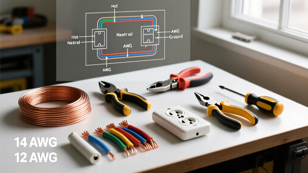
For a 30-amp circuit, NEC Table 310.16 requires a minimum of 10 AWG copper wire with a 75°C rating (THHN/THWN-2). You will need four individual conductors: Black (Hot 1), Red (Hot 2), White (Neutral), and Green (Ground). If you are running these wires through a 3/4-inch EMT conduit from the exterior inlet box to the interior MTS, the conduit fill is well within the 40% maximum limit dictated by NEC Chapter 9, Table 1.
Termination and Torque Specifications
A frequent failure point in DIY generator wiring is under-torqued terminal screws, which leads to high-resistance connections, arcing, and melted inlet blocks. When terminating the 10 AWG THHN wires into the PB30 inlet box:
- Strip exactly 3/4 inch of insulation from the conductors.
- Ensure no bare copper is exposed outside the terminal block.
- Tighten the terminal screws to the manufacturer's specified torque, typically 20 in-lbs for 10 AWG wire on standard 30A lugs. Use a calibrated torque screwdriver; guessing by hand is a violation of NEC 110.14(D), which mandates the use of a torque tool for terminals rated 100A or less.
Scenario 2: Using a Generator Interlock Kit with a 50-Amp Inlet
For larger homes utilizing a 10,000W+ generator with an L14-50R outlet, electricians often bypass a dedicated MTS in favor of a generator interlock kit (such as the Siemens ECSBPK01, priced around $60-$80) installed directly on the main service panel. This mechanical slider prevents the main utility breaker and the generator backfeed breaker from being turned on simultaneously.
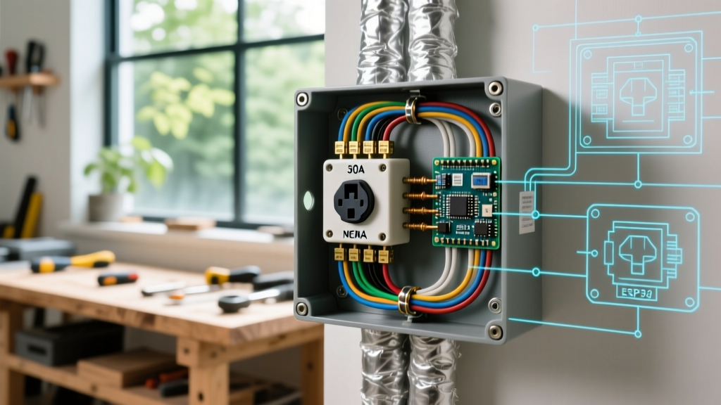
Expert Insight: When wiring a 50-amp inlet box like the Reliance Controls PB50, you must use 6 AWG copper THHN. Because 6 AWG is exceptionally stiff, pre-bending the conductors with a mechanical wire bender before pushing them through the 1-inch conduit knockout will save you from damaging the insulation or cracking the inlet box's PVC housing during termination.
In this scenario, the inlet box is wired directly to a 50-amp, 2-pole breaker in the main panel. The hot legs land on the breaker, the neutral lands on the neutral bar, and the ground lands on the equipment grounding bar. Never bond the neutral and ground in the inlet box or at the backfeed breaker. The main service panel is the only location where the neutral and ground bars are bonded in a residential system.
The #1 Edge Case: Neutral-Ground Bonding and GFCI Tripping
If you have perfectly wired your generator electrical outlet inlet box, but the generator's built-in GFCI breakers trip the moment you connect the load, you have encountered the infamous neutral-ground bonding conflict. This is the most heavily debated and misunderstood scenario in backup power wiring.
The Problem
Many modern portable generators feature a 'bonded neutral,' meaning the neutral wire is physically connected to the generator's metal frame (ground) at the alternator. Your home's main service panel also features a neutral-ground bond. When you connect the two via a standard 4-wire inlet box and a transfer switch that does not switch the neutral, you create a parallel path for neutral current to flow on the grounding wire. The generator's GFCI sensor detects this imbalance (current returning on the ground wire instead of the neutral) and instantly trips.
The Solutions
- Use a Switching Neutral MTS: Install a transfer switch that physically switches the neutral along with the hot legs (e.g., Reliance Controls 'X' series). This isolates the generator's bonded neutral from the house panel's bonded neutral.
- Float the Generator Neutral: Have a qualified technician remove the neutral-ground bonding screw or strap inside the generator's alternator housing, converting it to a 'floating neutral' machine. Warning: This alters the generator's safety profile when used standalone on a job site. Always follow FEMA and Ready.gov guidelines regarding portable generator grounding modifications.
- Remove the House Bond (Not Recommended): Never remove the neutral-ground bond at the main service panel. This violates fundamental NEC safety requirements and creates a lethal shock hazard.
Step-by-Step Physical Installation Sequence
To ensure a weatherproof and code-compliant installation, follow this precise sequence when mounting the exterior inlet box:
- Location Selection: Mount the inlet box at least 18 inches above grade to prevent snow or floodwater intrusion. Keep it within 15 feet of where the generator will sit to minimize voltage drop across the flexible cord.
- Core Drilling: Use a 1-inch masonry or wood hole saw to drill through the exterior wall. Feed a 10-inch piece of 3/4-inch PVC or EMT conduit through the hole to protect the wires from the siding and insulation.
- Weatherproofing: Apply a continuous bead of exterior-grade polyurethane sealant (such as OSI QUAD) behind the inlet box flange before securing it to the siding with stainless steel lag screws.
- Interior Transition: On the interior, use a 3/4-inch EMT-to-PVC transition fitting if running through a finished wall, ensuring the wires are protected all the way to the transfer switch or panel knockout.
- Final Verification: Before connecting the generator, use a digital multimeter to verify continuity between the inlet box ground terminal and the main panel ground bar. Verify no continuity exists between the inlet neutral and ground.
Summary and Code Compliance
Wiring a generator electrical outlet inlet system requires strict adherence to the NFPA 70 National Electrical Code. Whether you are executing a 30-amp MTS integration or a 50-amp interlock setup, the margin for error is zero. Always utilize torque screwdrivers for terminations, respect conduit fill capacities, and critically evaluate the neutral-ground bonding topology of your specific generator model. When in doubt, consult a licensed electrical contractor to perform the final panel termination and load balancing.