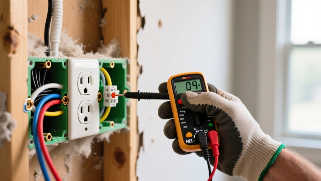

The Hidden Dangers of Untested Receptacles
Completing the physical wiring of a receptacle is only half the job. The true measure of a safe and compliant circuit lies in rigorous post-installation verification. According to the Consumer Product Safety Commission (CPSC), faulty receptacle wiring, loose neutrals, and improper grounding remain leading causes of residential electrical fires and shock hazards. When performing final checks on new electrical outlet installations, electricians and advanced DIYers must move beyond simple plug-in testers and adopt a systematic, multi-phase inspection protocol.
This guide details the exact methodologies, torque specifications, and diagnostic tools required to verify 15A and 20A, 120V receptacle installations against the latest National Electrical Code (NEC) standards.
Essential Diagnostic Arsenal
Standard three-light plug-in testers are insufficient for identifying high-impedance grounds or shared neutral faults. A professional inspection requires precision instruments.
- SureTest Circuit Analyzers (e.g., Ideal Industries 61-105): Priced around $160-$190, these devices measure actual ground impedance (in ohms) and verify GFCI trip times in milliseconds, rather than just relying on indicator lights.
- Fluke T5-600 Electrical Tester: Retailing for approximately $180, this tool allows for non-contact voltage detection and open-jaw current measurement, crucial for verifying load balance on multi-wire branch circuits.
- Calibrated Torque Screwdriver: A must-have for NEC compliance. The CDI 401SM or Klein Tools 32500 series (approx. $45-$60) ensures terminal screws are tightened to exact manufacturer specifications.
Phase 1: Visual and Mechanical Inspection
Before energizing the circuit, a thorough mechanical inspection prevents catastrophic failures that electrical testers cannot detect.
Box Fill and Conductor Management
Overcrowded junction boxes cause wire insulation damage and trap heat. Under NEC Article 314.16(B), you must calculate box fill based on conductor size. For standard 12 AWG wire, each current-carrying conductor requires 2.25 cubic inches of space. A standard single-gang deep box (22.5 cubic inches) can comfortably hold a receptacle, two 12/2 Romex cables (4 current-carrying conductors), and the internal clamps, but adding a third cable will violate box fill limits.
Wire Stripping and Terminal Torque
Exposed copper outside the terminal yoke creates a shock hazard, while insulation pushed under the screw causes a high-resistance connection that will eventually melt. Use the built-in wire gauge on the back of the receptacle (typically 5/8 inch for 15A/20A devices).
NEC 110.14(D) strictly mandates that terminals for 14, 12, and 10 AWG wires must be torqued to the manufacturer's specified values. For premium commercial-grade receptacles like the Hubbell HBL5262A or Leviton 5262, the required torque is exactly 14 inch-pounds. Failure to use a torque screwdriver is a direct code violation in most jurisdictions.
Phase 2: Electrical Verification and Fault Mapping
Once the circuit is energized, use a professional circuit analyzer to map the electrical characteristics of the installation. While basic testers use three neon lights, advanced analyzers provide digital readouts of line voltage, ground impedance, and wiring faults.
Common Wiring Faults and Tester Indications
The table below outlines how a standard Klein Tools RT250 GFCI receptacle tester interprets common installation errors. Note that 'Bootleg Grounds' (where the ground terminal is illegally jumpered to the neutral terminal) will often show a 'Correct' reading on basic testers, which is why advanced impedance testing is mandatory.
| Fault Condition | Left Light (Yellow) | Center Light (Yellow) | Right Light (Red) | Underlying Cause & Risk |
|---|---|---|---|---|
| Correct Wiring | ON | ON | OFF | Proper hot, neutral, and ground connections. |
| Open Ground | ON | ON | ON | Missing equipment ground; shock hazard if appliance faults. |
| Open Neutral | ON | OFF | OFF | Disconnected neutral; devices will not operate, voltage can float. |
| Hot/Neutral Reversed | OFF | ON | ON | Polarity reversed; shell of lamp fixtures becomes energized. |
| Hot/Ground Reversed | OFF | OFF | ON | Extremely dangerous; ground system is energized at 120V. |
Phase 3: GFCI, AFCI, and Ground Integrity Testing
Modern electrical outlet installations in kitchens, bathrooms, garages, and outdoor areas require Ground Fault Circuit Interrupter (GFCI) protection, while living areas and bedrooms require Arc Fault Circuit Interrupter (AFCI) protection.
Verifying GFCI Trip Thresholds
Under UL 943 standards, a Class A GFCI must trip when a ground fault current reaches between 4mA and 6mA. When using a SureTest analyzer, inject a 5mA fault. The digital display should show a trip time of less than 25 milliseconds. If the GFCI takes longer than 30ms to trip, the internal solenoid may be degrading, or there is excessive line impedance delaying the fault current.
AFCI Validation
AFCI protection is typically provided at the breaker panel rather than the receptacle itself. To test an AFCI breaker, you must press the physical 'Test' button on the breaker. Plug-in AFCI testers inject a specific high-frequency waveform to simulate an arc; however, the Occupational Safety and Health Administration (OSHA) and breaker manufacturers note that plug-in testers may not always trip older or specific brands of AFCI breakers due to signal attenuation over long wire runs. The mechanical breaker test button remains the only universally accepted verification method.
Advanced Edge Cases: MWBCs and Bootleg Grounds
Senior inspectors look for edge cases that bypass standard testing protocols. Two of the most dangerous are Multi-Wire Branch Circuits (MWBCs) and Bootleg Grounds.
Multi-Wire Branch Circuits (MWBC)
An MWBC shares a single neutral wire between two hot legs (Phase A and Phase B). If the two hot wires are accidentally connected to the same phase during installation, the shared neutral will carry the sum of both currents (e.g., 15A + 15A = 30A) on a wire rated for only 20A, leading to a hidden fire hazard inside the walls. Testing Protocol: Use a clamp meter (like the Fluke T5-600) around the neutral wire at the panel while both receptacles are under heavy load. The neutral current should be the difference between the two hot legs, ideally near zero if loads are balanced, never the sum.
Detecting the 'Bootleg Ground'
A bootleg ground occurs when an installer connects a short jumper wire between the neutral terminal and the ground terminal on a receptacle to trick a basic tester into showing a 'Correct' reading. Testing Protocol: Plug a high-wattage load (like a 1500W space heater) into the outlet. Use a true-RMS digital multimeter to measure the voltage drop between the neutral slot and the ground slot. On a properly wired circuit with an isolated ground, the voltage should remain below 0.5V. If the ground is bootlegged to the neutral, the voltage between the two slots will rise significantly (often 2V to 5V) as the return current flows through the jumper, creating a measurable potential difference.
Final Sign-Off and Documentation
Properly verifying electrical outlet installations requires moving past assumptions and relying on empirical data. By enforcing strict torque specifications, calculating box fill accurately, and utilizing advanced circuit analyzers to measure ground impedance and trip times, you ensure the installation is not only code-compliant but genuinely safe for decades of use. Always document your torque values and GFCI trip times on the final inspection ticket to provide a verifiable baseline for future electrical audits.
For the most up-to-date code requirements and safety bulletins, always consult the latest editions of the National Fire Protection Association (NFPA) codes and your local Authority Having Jurisdiction (AHJ).