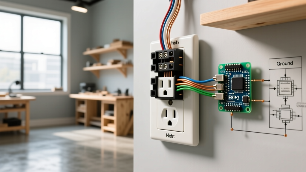

Understanding the Circuit Topology
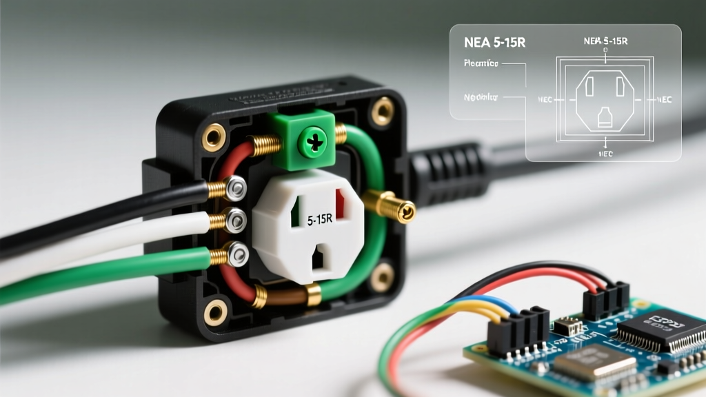
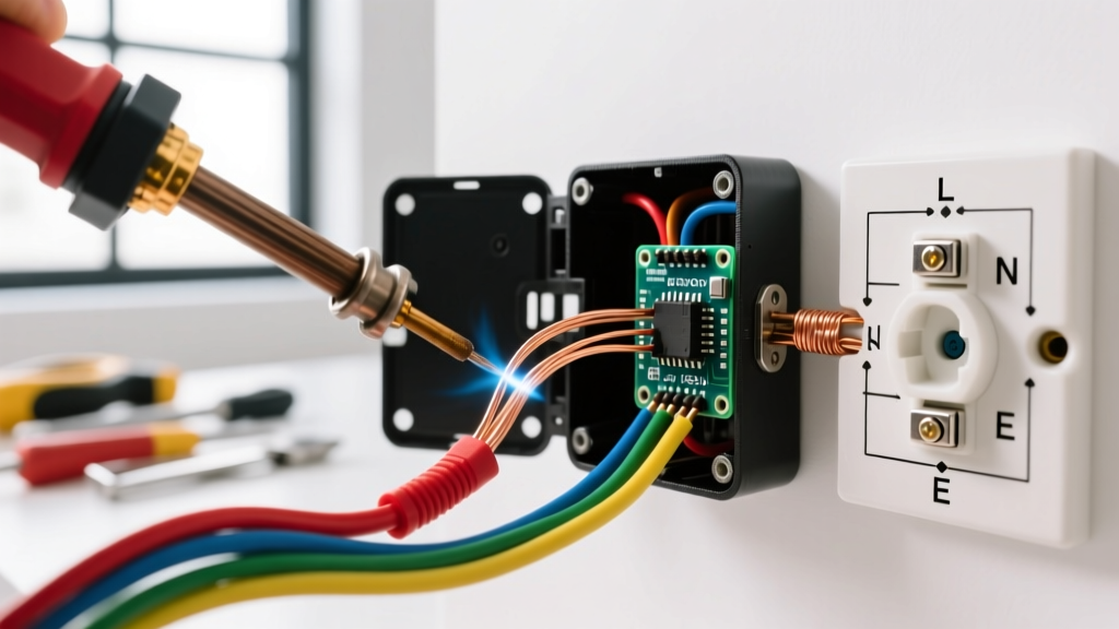
Wiring a light switch and a receptacle on the same circuit is one of the most common residential electrical tasks, frequently encountered when finishing a basement, adding a kitchen backsplash outlet, or wiring a bathroom vanity. However, interpreting a wiring diagram for light switch and outlet on same circuit requires a clear understanding of your specific topology. Are you feeding power to the switch first, or the outlet first? Does the switch control the light fixture while the outlet remains continuously hot, or does the switch control the receptacle itself?
In 2026, with the widespread adoption of the 2023 and upcoming 2026 National Electrical Code (NEC) cycles, understanding these diagrams is not just about functionality—it is about compliance, safety, and preventing arc faults. This guide provides a deep-dive, step-by-step installation protocol for the most common scenario: Power enters the box, the switch controls a separate light fixture, and the duplex receptacle remains always-hot.
⚠️ CRITICAL SAFETY WARNING: Always de-energize the circuit at the main breaker panel before beginning work. Verify zero voltage using a non-contact voltage tester (NCVT) and a digital multimeter. According to OSHA Electrical Safety Guidelines, failure to verify a de-energized state is a leading cause of residential electrical fatalities.
Scenario Matrix: What Are You Controlling?
Before stripping any wires, identify which circuit topology matches your project. The physical wiring diagram changes drastically based on the intended function.
| Topology Scenario | Switch Function | Outlet Function | Key Wiring Technique |
|---|---|---|---|
| Scenario A (Most Common) | Controls remote light | Always Hot | Hot pigtail to switch and receptacle |
| Scenario B | Controls top receptacle | Bottom is Always Hot | Break brass tab; feed switch loop |
| Scenario C | Controls entire outlet | Switched Hot | Line to switch, load to receptacle |
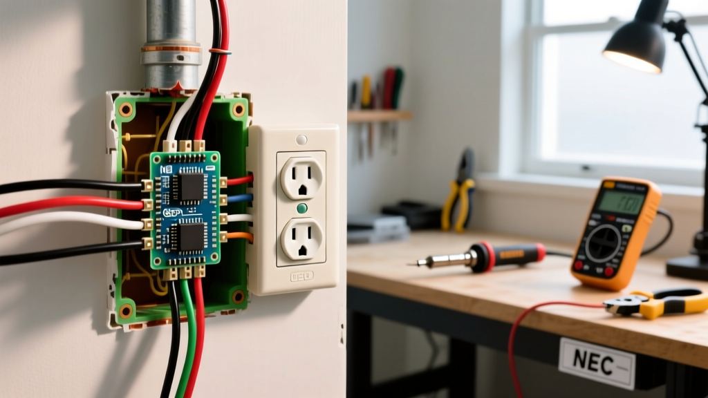
This guide focuses on the step-by-step installation of Scenario A, where power enters a double-gang box, feeding both a single-pole switch (for a ceiling light) and a standard duplex receptacle.
Required Tools and Materials
Professional-grade tools ensure secure terminations and prevent high-resistance connections that lead to thermal failure. Budget approximately $15 to $25 for the core components if you are starting from scratch.
- Receptacle: Leviton 5320-W 15A Tamper-Resistant (TR) Duplex ($1.30 - $1.80). TR is mandated by NEC 406.12 for all 15A and 20A residential receptacles.
- Switch: Leviton 1451-W 15A Single-Pole Toggle ($1.15).
- Wire Strippers: Klein Tools 11055 (specifically calibrated for 14 AWG and 12 AWG solid copper).
- Connectors: Ideal 341 Blue or 342 Yellow wire nuts, or Wago 221 series lever nuts (41-amp rated).
- Cable: 14/2 NM-B (Romex SIMpull) for 15A circuits, or 12/2 NM-B for 20A circuits.
- Testing: Klein NCVT-2 dual-range non-contact voltage tester and a Fluke 117 digital multimeter.
Step-by-Step Installation: Switch Controls Light, Outlet Always Hot
Step 1: Power Verification and Cable Prep
Shut off the 15A or 20A breaker at the panel. Test the existing wires in the box with your NCVT-2. Once verified dead, prepare your incoming 14/2 NM-B line cable, your 14/2 load cable (running to the light fixture), and your 14/2 feed-through cable (if daisy-chaining to the next outlet).
Strip exactly 3/4 inch of insulation from the black and white conductors. Stripping less than 5/8 inch results in the wire nut failing to bite the copper; stripping more than 7/8 inch leaves exposed, uninsulated copper outside the connector, creating a severe shock and short-circuit hazard.
Step 2: Grounding and Neutral Splicing
NEC Article 250 requires all equipment grounding conductors (EGCs) to be bonded. Gather all bare copper ground wires (line, load, and feed-through). Add a 6-inch 14 AWG bare copper pigtail. Secure them with a green wire nut or a Wago 221 lever connector. Attach the pigtail to the green grounding screw on the Leviton 5320-W receptacle. Note: Standard single-pole switches do not require a ground wire unless they are metal-yoke, smart switches, or equipped with an internal grounding screw, but best practice in 2026 is to always land a ground pigtail on the switch's green screw if present.
Next, splice all white neutral wires together using a yellow Ideal 342 wire nut. Add a 6-inch white pigtail and connect it to the silver (white) terminal on the receptacle. The switch does not connect to the neutral bundle in a standard single-pole light switch configuration.
Step 3: The Hot Pigtail Method
This is the most critical step in the wiring diagram for a light switch and outlet on the same circuit. Because the incoming hot (black) wire must feed both the always-hot receptacle and the switch, you cannot simply daisy-chain them using the device's internal brass jumper. You must use a hot pigtail.
- Take your incoming black (hot) line wire and any black feed-through wires heading to downstream outlets.
- Add a 6-inch black 14 AWG pigtail. Splice them all together with a wire nut.
- Take a second 6-inch black pigtail and add it to the same splice bundle. (Alternatively, use a Wago 5-port 221 connector for a cleaner, more reliable termination).
- Connect the first black pigtail to the brass (gold) terminal on the receptacle.
- Connect the second black pigtail to the brass terminal on the single-pole switch.
- Connect the black wire from your 14/2 load cable (the cable running up to the ceiling light) to the second brass terminal on the switch.
Pro-Tip (Torque Specs): While residential DIYers rarely use torque screwdrivers, Leviton specifies a terminal torque of 14 in-lbs for their 15A devices. Under-torquing leads to thermal cycling and loose connections; over-torquing strips the brass threads. Hand-tighten firmly until the wire is immovable, then give it an extra quarter-turn.
Alternative Topology: Switch Controls the Receptacle
If your goal is to have the wall switch control a table lamp plugged into the outlet (Scenario B), the wiring diagram changes. You will not use a hot pigtail. Instead:
- Connect the incoming black hot wire directly to the switch.
- Run a black jumper from the switch to the top brass terminal on the receptacle.
- Use a pair of needle-nose pliers to snap off the small brass connecting tab between the top and bottom brass terminals on the receptacle. Do not break the silver neutral tab.
- Connect the incoming black feed-through to the bottom brass terminal so the bottom half remains always-hot.
NEC Compliance and Box Fill Calculations
A frequent failure mode in DIY wiring is cramming too many wires into a standard single-gang or shallow double-gang box, violating NEC Article 314 box fill calculations. Overcrowded boxes cause wire insulation damage and trap heat.
For 14 AWG wire, each conductor counts as 2.0 cubic inches. A standard double-gang steel box is typically 18 to 21 cubic inches. If you have a line, a load to the light, and a feed-through to another outlet, you have 6 current-carrying conductors (12 cu in), 1 device yoke for the switch (4 cu in), 1 device yoke for the receptacle (4 cu in), and equipment grounds (2 cu in). Total required volume: 22 cubic inches. A standard 18-cubic-inch double-gang box is illegal and unsafe for this topology. Always use deep 4-inch square boxes with a double-gang mud ring (yielding 34+ cubic inches) or deep PVC double-gang boxes rated for at least 24 cubic inches.
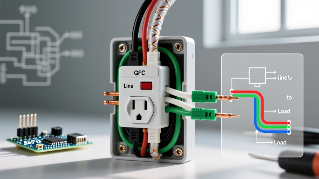
Furthermore, as jurisdictions adopt the latest National Electrical Code (NEC) standards, AFCI (Arc-Fault Circuit Interrupter) protection is mandatory for almost all living spaces, and GFCI protection is required in wet locations. If this circuit serves a kitchen or bathroom, the receptacle must be GFCI protected, which alters the wiring diagram significantly (requiring line/load differentiation on a GFCI receptacle).
Troubleshooting Common Failure Modes
If you have completed the wiring but the circuit is malfunctioning, check these specific edge cases:
- The Outlet Works, But the Light Won't Turn On: Check the switch loop. Did you accidentally connect the light's white neutral wire to the switch instead of the neutral bundle? Use a multimeter to verify 120V between the switch's load terminal and ground when the switch is ON.
- The Breaker Trips Immediately: You likely created a dead short. This happens if the bare copper ground wire is touching the brass hot terminal on the receptacle or switch. Ensure all bare ground wires are pushed deep into the back of the box.
- Downstream Outlets Are Dead: You failed to include the feed-through black and white wires in your main splice bundles, or a wire nut has vibrated loose. Tug-test every wire nut; the wire should not pull out.
- Backstabbing Failures: Never use the push-in 'backstab' terminals on the back of the Leviton 5320-W or 1451-W. These rely on a tiny spring-metal wedge that loosens over time due to thermal expansion and contraction, causing arcing. Always use the side-binding screw terminals or the rear pressure-clamp plates.
Frequently Asked Questions
Can I use 14/2 wire on a 20-amp breaker for this setup?
No. NEC Article 240.4 strictly prohibits 14 AWG copper wire on a 20-amp overcurrent protection device. If your breaker is 20A, you must use 12/2 NM-B cable and a 20A rated receptacle (like the Leviton 5362-W). The switch can remain 15A rated, as it only handles the lighting load, but the receptacle must be 20A.
Do I need a GFCI outlet if this is in a garage?
Yes. The U.S. Consumer Product Safety Commission and the NEC mandate GFCI protection for all 125V, 15A, and 20A receptacles in garages, unfinished basements, and outdoor locations. If the switch and outlet share a box in a garage, the receptacle must be a GFCI model, while the switch remains a standard toggle.
Why does my LED light flicker when the switch is off?
This is not a wiring diagram error, but a component mismatch. Many modern smart switches or illuminated toggle switches leak a tiny amount of current (1-2mA) through the circuit to power their internal LED indicator. This micro-current charges the capacitor in LED bulbs, causing them to strobe. The fix is to install an Lutron LUT-MLC capacitor across the light fixture's line and load, or switch to high-quality LED bulbs with built-in bleed resistors.