
The Critical Link: Why Outlet-to-Breaker Mapping Matters
Every DIY electrician and homeowner eventually faces a frustrating scenario: an electrical outlet circuit breaker trips, but the panel directory is either blank, faded, or notoriously inaccurate. Working on a receptacle without verifying its exact breaker mapping is a severe safety hazard that can lead to arc flashes or fatal shocks. Furthermore, as we navigate the 2026 National Electrical Code (NEC) adoption cycles, understanding the nuanced relationship between your outlets and their corresponding panel breakers—especially regarding AFCI and GFCI protections—is no longer optional; it is a strict legal and safety requirement.
This inspection and testing guide goes beyond basic trial-and-error. We will cover professional-grade circuit tracing, load-testing methodologies, thermal-magnetic trip curve analysis, and advanced troubleshooting matrices to ensure your electrical outlet circuit breaker setup is safe, compliant, and fully functional.
Essential Diagnostic Tools for 2026
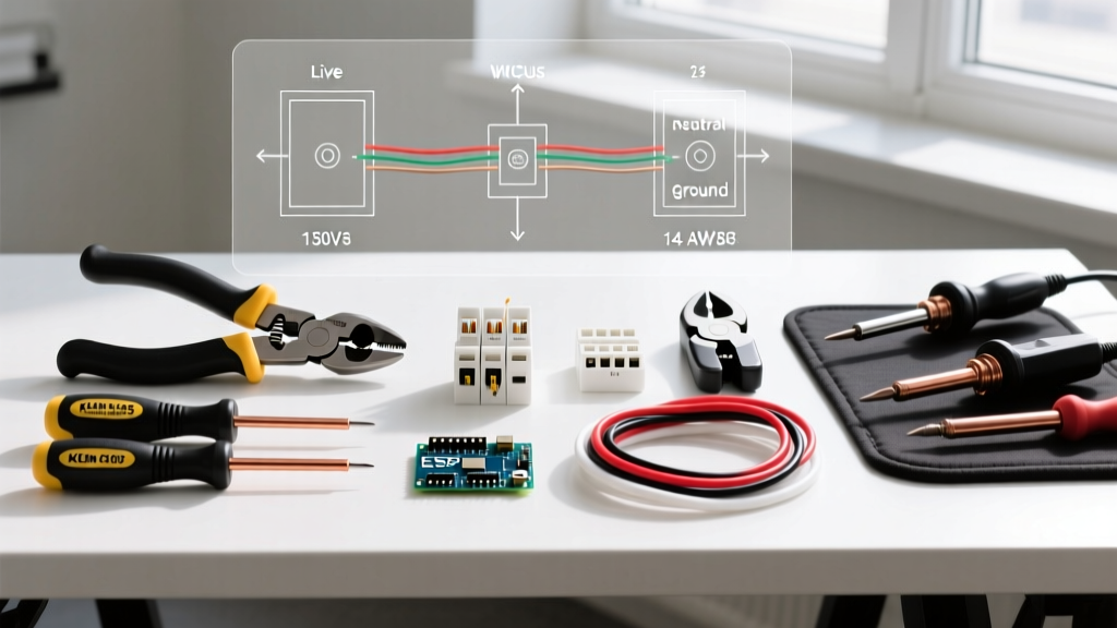
Before opening a single junction box, you need the right diagnostic equipment. Relying solely on a basic neon voltage tester is insufficient for modern electrical systems.
- Circuit Breaker Finder (e.g., Amprobe BT-120 or Klein Tools ET900): Priced around $45 to $60, these tools inject a modulated signal into the receptacle, allowing the receiver to identify the exact breaker emitting that frequency at the panel.
- True RMS Digital Multimeter (e.g., Fluke 117 or Klein Tools MM600): Essential for measuring exact voltage drop under load. Budget models ($30) fail to read non-linear loads accurately; invest in a True RMS meter ($150–$220).
- Advanced Receptacle Tester (e.g., Klein Tools RT310): At roughly $25, this tool doesn't just check wiring correctness; it features a dedicated button to trip GFCI circuits and measures the exact trip time of the breaker or receptacle.
- Insulation Resistance Tester (Megger): For advanced diagnostics, a tool like the Fluke 1587 ($600+) helps identify degrading wire insulation that causes nuisance breaker trips.
Step-by-Step Electrical Outlet Circuit Breaker Mapping
Accurate mapping requires a systematic approach. Never assume a bedroom outlet is on the bedroom breaker; builders frequently daisy-chain circuits across multiple rooms to save wire.
Method 1: The Signal Injection Technique (Preferred)
- Plug the transmitter of your circuit breaker finder (e.g., Amprobe BT-120) into the target electrical outlet.
- Verify the transmitter LED is solid, indicating a proper 120V connection.
- Go to your main service panel and turn on the receiver.
- Slowly scan the receiver's sensor tip over the face of the breakers. The device will emit a rapid beep and visual indicator when it detects the injected signal.
- Pro Tip: Scan the breaker twice. The first pass identifies the signal; the second pass confirms it, ruling out cross-talk from adjacent breakers.
Method 2: The Load-Bank Drop Test (For Unlabeled Panels)
If you lack a signal tracer, plug a high-draw resistive load (like a 1500W space heater or a 100W incandescent drop light) into the outlet. Connect a True RMS multimeter to the bus bar or a known reference point at the panel. Have a helper switch the load on and off while you monitor for micro-voltage fluctuations on the panel's main lugs, though this is significantly less accurate than Method 1.
Load Testing and the 80% Continuous Rule
Once you have identified the electrical outlet circuit breaker, you must verify it is correctly sized for the wire gauge and the expected load. The NEC strictly enforces the 80% rule for continuous loads (loads expected to run for 3 hours or more).
| Breaker Rating | Minimum Copper Wire (AWG) | Max Absolute Trip (Thermal) | Max Continuous Load (80%) | Common Outlet Applications |
|---|---|---|---|---|
| 15 Amp | 14 AWG | ~18-20 Amps | 12 Amps (1440W) | Bedrooms, Living Rooms, Hallways |
| 20 Amp | 12 AWG | ~24-26 Amps | 16 Amps (1920W) | Kitchens, Bathrooms, Garages, Outdoors |
| 30 Amp | 10 AWG | ~36-40 Amps | 24 Amps (2880W) | Dryers, Water Heaters (No standard 15/20A outlets) |
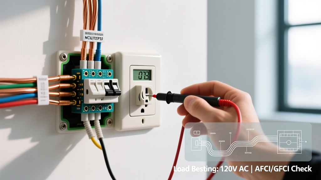
Voltage Drop Inspection: Measure the voltage at the outlet with no load (should be 120V-124V). Then, plug in a 12A load (like a hairdryer) and measure again. If the voltage drops below 114V (a 5% drop), your wire run is too long for its gauge, or you have high-resistance connections (like corroded backstabbed terminals) generating heat upstream of the breaker.
Navigating AFCI and GFCI Breaker Nuances
Modern electrical outlet circuit breaker troubleshooting is heavily complicated by Arc Fault Circuit Interrupters (AFCI) and Ground Fault Circuit Interrupters (GFCI). According to the NFPA 70 National Electrical Code, AFCI protection is now mandated in virtually all habitable living spaces, while GFCI protection is required in damp or wet locations.
Safety Warning: A standard thermal-magnetic breaker will NOT protect you from a ground fault (shock hazard) or a parallel arc fault (fire hazard). Never replace a tripping AFCI/GFCI breaker with a standard breaker to 'solve' a nuisance trip. This is a severe code violation and fire hazard.
Testing the Breaker vs. The Receptacle
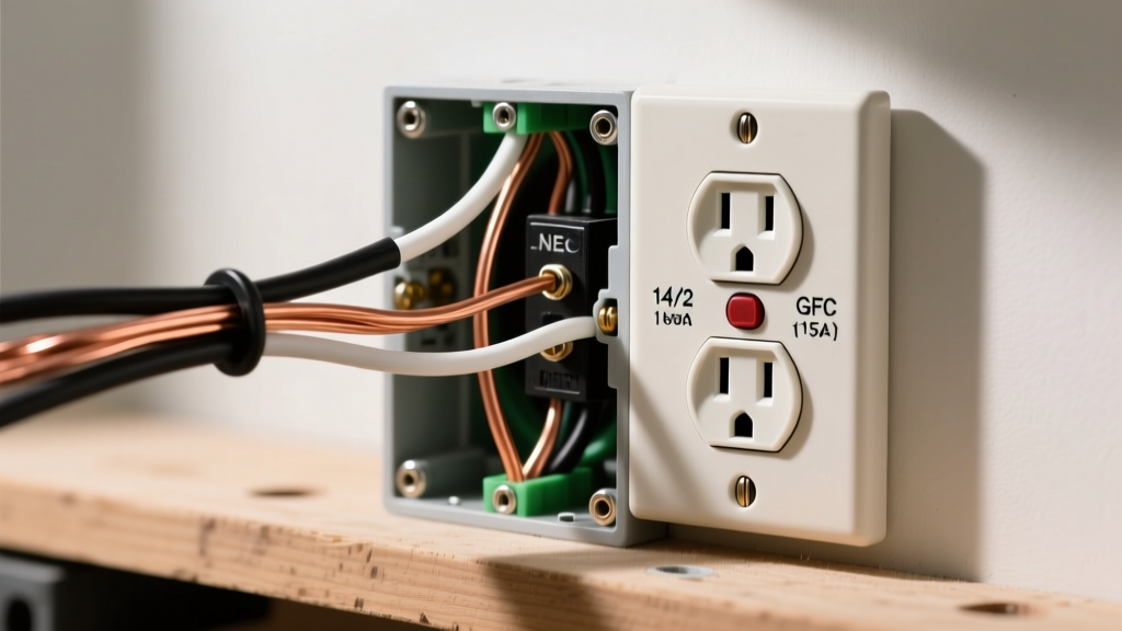
Protection can exist at the panel (breaker) or at the outlet (receptacle). If your panel has an AFCI breaker (identifiable by a colored Test button and a coiled wire pigtail connecting to the neutral bar), pressing the 'Test' button on the breaker should immediately cut power to the entire circuit. If you have a GFCI receptacle downstream, pressing its local test button should only kill power to that specific outlet and any downstream daisy-chained outlets, leaving the breaker intact.
For deeper insights into arc fault technology and fire prevention, the Electrical Safety Foundation International (ESFI) provides extensive data on how AFCIs detect dangerous arcing conditions that standard breakers miss. Similarly, the U.S. Consumer Product Safety Commission (CPSC) notes that AFCIs can prevent more than 50% of electrical fires that occur annually in the United States.
Troubleshooting Matrix: Breaker and Outlet Failure Modes
When an electrical outlet circuit breaker fails or trips, the timing and nature of the trip reveal the exact root cause. Use this diagnostic matrix to isolate the fault.
| Symptom / Behavior | Probable Root Cause | Diagnostic Action & Solution |
|---|---|---|
| Instantaneous Trip: Breaker snaps off immediately with a loud pop upon resetting. | Dead Short Circuit (Hot touching Ground or Neutral). | Unplug all devices. Inspect the outlet for melted plastic. Check for a drywall nail pierced through the Romex cable. Use a multimeter in continuity mode to find the short. |
| Delayed Thermal Trip: Breaker holds for 10–45 minutes, then trips. | Continuous Overload (Exceeding 80% capacity) or Loose Neutral. | Measure amp draw with a clamp meter. Check for loose neutral wires at the panel bus bar causing resistance and heat, which tricks the breaker's thermal bimetallic strip. |
| Nuisance AFCI Trip: AFCI breaker trips randomly when a vacuum or treadmill is turned on. | False Arc Detection from brushed motors or shared neutrals. | Verify no multi-wire branch circuits (MWBC) are sharing a neutral incorrectly. Replace older appliances with heavy EMI (electromagnetic interference). |
| Outlet Dead, Breaker 'ON': Receptacle has no power, but breaker handle is in the ON position. | Upstream GFCI Trip, Backstab Failure, or Broken Conductor. | Reset all GFCI outlets in adjacent rooms/bathrooms. Remove the dead outlet and check if wires were pushed into the backstab holes; move them to the screw terminals. |
Advanced Inspection: Checking for Breaker Fatigue
Circuit breakers are mechanical devices with a finite lifespan. A standard Square D Homeline or Eaton BR breaker is rated for roughly 4,000 to 6,000 mechanical operations. However, if a breaker has been used as a light switch (which violates NEC guidelines for standard breakers not rated for SWD - Switching Duty), the internal contacts may become pitted and carbonized.
The Voltage Drop Test Across the Breaker:
With the panel covers removed (extreme caution required; use insulated tools and PPE), set your True RMS multimeter to AC Voltage. Place one probe on the breaker's output terminal (the screw where the hot wire connects) and the other on the bus bar stab that the breaker clips onto. Under a moderate load (e.g., 10 Amps), the voltage drop across the breaker itself should be less than 0.5 Volts. If you read 2V or higher, the breaker's internal contacts are degraded, generating excess heat, and the breaker must be replaced immediately.
Final Thoughts on Code Compliance
Inspecting and testing your electrical outlet circuit breaker setup is an exercise in both immediate safety and long-term compliance. As smart panels (like the Leviton Smart Load Center or Span Drive) become more prevalent in 2026, the ability to digitally monitor individual breaker health and load metrics via smartphone apps is reducing the need for manual clamp-meter diagnostics. However, the foundational physics of thermal-magnetic trips, wire gauge limitations, and AFCI/GFCI protections remain unchanged. Always verify your mappings, respect the 80% continuous load rule, and never bypass a tripping safety device to restore power.