
Decoding the Wiring Diagram for a Four Way Light Switch
When a single lighting fixture needs to be controlled from three or more locations, a standard 3-way switch setup is no longer sufficient. You must introduce a 4-way switch into the circuit. For electrical inspectors, DIYers, and journeyman electricians, understanding the exact wiring diagram for a four way light switch is critical for both initial installation and ongoing troubleshooting. Unlike a standard single-pole switch that simply breaks the hot leg, a 4-way switch acts as a reversing polarity valve for the traveler wires passing between two 3-way switches.
In a standard 2026 residential topology, the circuit flows as follows: Power Source ➔ 3-Way Switch (Line) ➔ Traveler Pair ➔ 4-Way Switch ➔ Traveler Pair ➔ 3-Way Switch (Load) ➔ Lighting Fixture. The 4-way switch sits squarely in the middle of the traveler run. Its internal mechanical contacts either pass the electrical current straight through (parallel) or cross the connections (X-pattern), depending on the toggle position. If you are inspecting an existing circuit that is failing to operate correctly from all locations, you must isolate the 4-way switch and test its internal continuity against the wiring diagram.
Code Compliance Note: According to the National Electrical Code (NEC) via NFPA, travelers are not strictly required to be a specific color, but they must be identified. Best practice in the field is to re-identify traveler wires using yellow or purple electrical tape to distinguish them from line, load, and neutral conductors during inspection.
Required Testing Equipment for 2026 Standards
Before opening any junction box or pulling a switch yoke from the wall, you must gather the appropriate diagnostic tools. Relying on a basic non-contact voltage tester is insufficient for continuity testing. You will need:
- Fluke T5-1000 Electrical Tester ($185 - $210): The industry standard for verifying the absence of voltage and testing continuity without needing to strip wire insulation for basic checks.
- Klein Tools NCVT-3 Non-Contact Voltage Tester ($35): Used for the initial sweep of the junction box to detect stray voltage or backfed currents from smart home leakage.
- Standard Digital Multimeter (DMM): Must feature an audible continuity beep and an Ohms (Ω) setting. Models like the Fluke 117 or Klein MM400 are highly recommended.
- Lockout/Tagout (LOTO) Kit: Mandatory for securing the breaker panel. Adherence to OSHA Lockout/Tagout standards is non-negotiable, even in residential settings, to prevent accidental re-energization while your hands are in the box.
Step-by-Step Inspection and Continuity Testing
To properly inspect the 4-way switch, you must remove it from the circuit to eliminate parallel resistance paths and phantom voltages. Follow this exact sequence:
Step 1: De-energize and Verify
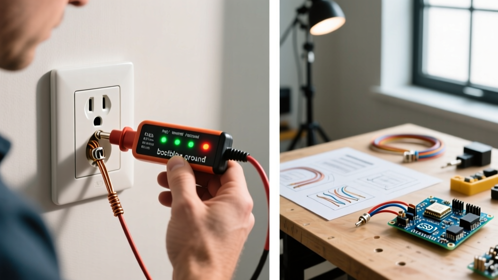
Turn off the corresponding breaker at the main panel. Apply your LOTO device. Use the NCVT-3 to scan the switch plate and wires. Then, use the Fluke T5-1000 to test between the known ground and every terminal on the 4-way switch to confirm 0V. A 4-way switch has four traveler terminals and a ground screw. It does not have a common (dark-colored) terminal like a 3-way switch.
Step 2: Disconnect and Label
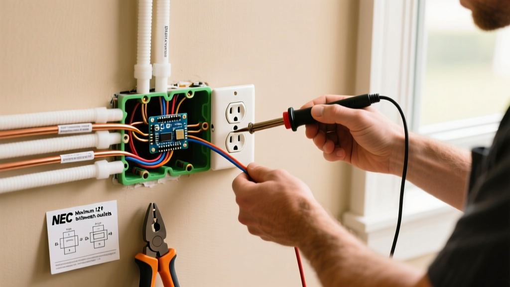
Remove the four traveler wires from the brass/dark terminals. Crucial Inspection Tip: Label the incoming traveler pair (from the line-side 3-way) as 'T1' and 'T2', and the outgoing traveler pair (to the load-side 3-way) as 'T3' and 'T4'. This matches the standard wiring diagram for a four way light switch and prevents cross-wiring during reassembly.
Step 3: The Continuity Matrix Test
Set your multimeter to the continuity (audible beep) or Ohms setting. Place one probe on T1 and the other on T3. Toggle the switch. The meter should beep in one position and go silent in the other. Next, move the probe from T3 to T4. The behavior should invert.
A healthy 4-way switch (such as a Leviton 5604-2W or Eaton 744W) will exhibit the following internal logic:
- Position A (Straight): T1 connects to T3; T2 connects to T4.
- Position B (Crossed): T1 connects to T4; T2 connects to T3.
If your multimeter shows infinite resistance (OL) in both toggle positions for any given pair, the internal copper contact wipers are carbon-scored or broken, and the switch must be replaced. According to National Electrical Manufacturers Association (NEMA) standards, residential toggle switches are rated for tens of thousands of cycles, but arc pitting from high-inrush LED drivers can degrade contacts prematurely.
Troubleshooting Matrix: Symptoms vs. Wiring Faults
When the physical switch tests fine, the fault lies in the wiring topology or the terminal 3-way switches. Use this diagnostic matrix to map the symptom to the specific failure point in the wiring diagram.
| Observed Symptom | Probable Failure Point | Inspection Action Required |
|---|---|---|
| Light only works from one specific 3-way switch location. | Broken traveler wire or miswired common terminal on the opposing 3-way switch. | Perform end-to-end continuity test on traveler wires. Verify the dark 'Common' screw holds the Line or Load, not a traveler. |
| Light works from the 3-ways, but the 4-way switch does nothing. | Travelers wired to the same side of the 4-way (e.g., T1 and T2 on the input side). | Verify the wiring diagram: Input pair must be on one set of terminals, Output pair on the other. Do not mix pairs on the same side. |
| Breaker trips immediately when any switch is toggled. | Ground fault or hot-to-neutral short in a junction box. | Inspect all wire nuts. Check for pinched insulation where the yoke was pushed back into the metal junction box. |
| Flickering or dimming when the 4-way is in one specific position. | Carbon buildup on the internal 4-way contacts causing high resistance. | Replace the 4-way switch. Do not attempt to clean internal contacts; they are sealed and riveted. |
Inspecting Junction Box Fill and Wire Nut Torque
A 4-way switch box is notoriously crowded. It houses the switch itself, four traveler wires, a ground, and often a neutral splice (even if the switch doesn't use it, NEC 404.2(C) requires a neutral at switch boxes for smart switch readiness). During your inspection, you must calculate the box fill.
Under NEC Article 314.16, a standard single-gang box (18 cubic inches) is frequently overfilled when accommodating a 4-way switch and four 14 AWG or 12 AWG travelers. If you are inspecting a retrofit, look for 'old work' boxes that have been expanded or check for the use of deep 2.5-inch masonry or metallic boxes. Furthermore, perform a physical pull-test on all wire nut connections. Using Ideal Industries Yellow Wing-Nuts (Model 341), the connection should withstand a firm 5-pound pull without the copper conductor slipping out. Loose travelers will cause intermittent arcing, leading to the flickering symptoms noted in the matrix above.
Edge Case: Upgrading to Smart Switches (Bypassing the 4-Way)
As of 2026, the most common reason homeowners request an inspection of a 4-way circuit is to upgrade to smart lighting, such as the Lutron Caseta system. Standard smart switches (like the Caseta PD-5WS-DV) cannot be wired directly into the middle of a 4-way traveler loop.
If your inspection reveals a client attempting to wire a smart switch into the 4-way position using the travelers, flag it as a critical violation. The correct methodology requires installing the smart switch at the Line or Load 3-way location, capping the travelers in the other boxes, and using wireless Pico remotes mounted to the wall plates at the 4-way and opposing 3-way locations. Understanding this bypass logic is a vital part of modern electrical inspection and saves hours of frustrating troubleshooting with incompatible wiring diagrams.
Frequently Asked Questions (FAQ)
Can I use a 4-way switch to control a ceiling fan?
Yes, but you must ensure the switch is rated for the inductive load of the fan motor. Standard 15A/120V AC toggle switches are generally sufficient for standard residential fans, but if the fan includes high-draw lighting arrays, verify the total amperage does not exceed 80% of the switch rating.
Why does my wiring diagram show a neutral wire connected to the 4-way switch?
Standard mechanical 4-way switches (like the Eaton 744W) do not use a neutral wire. If you see a neutral pigtailed to a switch terminal, it is likely an illuminated toggle switch (which requires a tiny amount of current to power the internal LED locator light) or a miswired smart switch attempt. Always verify the manufacturer's spec sheet.
What happens if I swap the input and output travelers on the 4-way switch?
Electrically, a standard 4-way switch is bidirectional. Swapping the incoming line-side travelers with the outgoing load-side travelers on their respective terminal pairs will not affect the operation of the circuit. However, for inspection consistency and future troubleshooting, always adhere to the logical flow of the wiring diagram.