
The Legal Framework: Why Your Trailer Wiring Must Meet Federal Code
While searching for a basic wiring diagram for 4 pin trailer plug configurations might seem like a straightforward weekend DIY task, improper execution violates federal safety regulations and risks catastrophic failure on the highway. As of 2026, the Department of Transportation (DOT) and the Federal Motor Carrier Safety Administration (FMCSA) have heavily increased roadside inspection scrutiny on trailer lighting circuits, particularly regarding voltage drop and improper splicing.
This guide moves beyond generic color-matching charts. We will dissect the exact code requirements governing 4-way flat connectors, explore the engineering standards for automotive wire, and provide a code-compliant methodology for terminating your trailer lighting circuit.
The Anatomy of a 4-Way Flat Connector: SAE Color Matrix
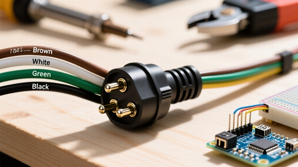
The 4-pin flat connector remains the undisputed standard for light-duty trailers (under 10,000 lbs GVWR) in North America. The pinout is standardized by the Society of Automotive Engineers (SAE) and the RV Industry Association (RVIA). Below is the definitive code-compliant matrix for wire routing and load expectations.
| Pin Position | Function | SAE Standard Wire Color | Max Amp Draw (Incandescent) | Max Amp Draw (LED) |
|---|---|---|---|---|
| 1 (Left/Exposed) | Ground (Return Path) | White | N/A (Handles total circuit return) | N/A |
| 2 | Tail / Running Lights | Brown | 8A - 12A | 1A - 2A |
| 3 | Left Turn / Stop Lamp | Yellow | 4A - 6A | 0.5A - 1A |
| 4 | Right Turn / Stop Lamp | Green | 4A - 6A | 0.5A - 1A |
Federal Code Requirements: FMVSS 108 Compliance
The overarching legal mandate for trailer lighting in the United States is 49 CFR § 571.108 (FMVSS 108). This standard dictates not just the presence of lights, but their photometric output (candela) and illumination latency.
The Voltage Drop Violation
Under FMVSS 108, stop lamps must illuminate to their minimum required candela within 200 milliseconds of brake application. If your wiring diagram for 4 pin trailer plug setups utilizes undersized wire over a long run, voltage drop will dim the bulbs and delay filament heating, rendering the trailer non-compliant and legally liable in the event of a rear-end collision.
Expert Insight: Many DIYers assume 18 AWG wire is sufficient because it 'fits the pin.' However, running 18 AWG wire over a 25-foot trailer chassis can result in a 1.5V to 2V drop under incandescent loads, dropping the bulb voltage below the 11V threshold required for legal photometric output.
Wire Insulation Standards: SAE J1128 vs. PVC
A critical, often overlooked code requirement involves the wire insulation itself. Standard hardware-store PVC (polyvinyl chloride) wire is not rated for mobile, under-chassis environments. The SAE J1128 Low Tension Primary Cable Standard mandates that surface vehicle electrical cable must resist specific automotive fluids, UV degradation, and extreme thermal cycling.
Approved Wire Types for 2026 Trailer Builds
- GXL (General Cross-Linked): The industry standard for trailer harnesses. Features a thick, cross-linked polyethylene insulation that resists melting against hot exhaust components and resists battery acid.
- TXL (Thin Cross-Linked): Offers the same chemical and thermal resistance as GXL but with a thinner insulation wall, ideal for routing through tight chassis channels where weight and flexibility are priorities.
- SGT (Standard Gauge Trailer): Specifically manufactured for battery and ground cables in heavy-duty towing applications.
Calculating Wire Gauge for Code-Compliant Runs
To ensure your wiring diagram for 4 pin trailer plug configurations meets FMCSA Part 396 inspection requirements, you must size the wire based on the total circuit length (from the tow vehicle battery/alternator to the furthest trailer taillight) and the total amperage.
Ampacity & Gauge Sizing Chart (12V DC System)
| Total One-Way Wire Length | 14 AWG (GXL) Max Load | 12 AWG (GXL) Max Load | 10 AWG (GXL) Max Load |
|---|---|---|---|
| Under 15 Feet | 15 Amps | 20 Amps | 30 Amps |
| 15 to 25 Feet | 10 Amps | 15 Amps | 25 Amps |
| 25 to 40 Feet | 7 Amps | 12 Amps | 20 Amps |
Note: If you have upgraded to modern LED trailer lights (like the Optronics Fleet LED series), your amperage draw is reduced by up to 85%, allowing for longer runs on smaller gauge wire without violating voltage drop thresholds.
Code-Compliant Termination: Banning the Wire Nut
The most common failure point in trailer wiring—and an immediate red flag during DOT roadside inspections—is the use of twist-on wire connectors (wire nuts) or standard vinyl electrical tape. Mobile environments subject wires to high-frequency vibration, moisture, and road salt.
The Mandated Termination Protocol
- Strip to Exact Length: Use a precision wire stripper to remove exactly 1/4 inch of insulation. Nicking the copper strands reduces the wire's cross-sectional area and creates a localized heat point.
- Use Adhesive-Lined Heat Shrink Butt Connectors: Standard vinyl crimps will wick moisture via capillary action, leading to green copper oxide corrosion within months. Polyolefin heat-shrink connectors with an inner melamine adhesive seal the wire completely.
- Crimp, Then Heat: Use a ratcheting crimp tool (such as the Astro Pneumatic 106) that meets IPC/WHMA-A-620 standards for wire harness acceptance. Apply heat from the center outward to force the adhesive out of the ends, ensuring a watertight seal.
- Apply Dielectric Grease: Before mating the 4-pin flat connector (e.g., the Hopkins Endurance HM48030), pack the female terminals with a lithium-based dielectric grease to prevent galvanic corrosion between the copper and brass terminals.
The 'Hitch Ball Ground' Fallacy
A pervasive myth in trailer wiring is that the white ground wire (Pin 1) is merely a backup, and that the primary ground is achieved through the steel hitch ball. This violates electrical best practices and guarantees intermittent failure.
The hitch ball relies on friction between the coupler and the ball, which is constantly subjected to rust, road grime, and kinetic bouncing. When the ground path through the hitch fails, the circuit attempts to find an alternate path to ground. This results in 'backfeed,' where applying the brakes causes the running lights to illuminate, or turning left causes the right tail light to flash. The white ground wire must be securely bolted directly to the trailer's bare steel chassis using a star washer to bite through the paint and powder coating.
Frequently Asked Questions (FAQ)
Can I use a 4-pin to 7-pin adapter for electric brakes?
No. A 4-pin connector lacks the dedicated 12V auxiliary power pin and the electric brake controller output pin required by code for trailers equipped with electric brakes. You must rewire the trailer harness to a native 7-way RV blade connector (SAE J289 standard).
Why do my trailer lights work when unplugged from the truck, but short out when connected?
This is a classic ground loop issue. The trailer's internal ground is tied to a painted surface, forcing the return current to backfeed through the truck's wiring harness. Scrape the trailer frame to bare metal at the white wire grounding point and secure it with a self-tapping stainless steel screw.
Is it legal to splice a damaged trailer harness mid-run?
While not explicitly banned by FMVSS 108 if done correctly, the FMCSA strongly discourages mid-harness splices due to vibration fatigue. If a splice is unavoidable, it must be performed using the adhesive-lined heat shrink method detailed above and secured to the chassis with UV-rated zip ties to prevent strain on the crimp joint.