
Diagnosing the Need for an Ignition Switch Upgrade
When a riding lawn mower refuses to crank, or conversely, when the engine continues to run after you turn the key to the OFF position, the primary suspect is often the ignition switch. Over time, internal copper contacts degrade, moisture infiltrates the plastic housing, and the mechanical detents wear out. For DIYers and small engine technicians, understanding the ignition switch wiring diagram for lawn mower applications is the critical first step in performing a safe, reliable replacement or upgrading to a heavy-duty, weather-sealed unit.
According to the Outdoor Power Equipment Institute (OPEI), improper electrical bypassing or incorrect switch replacement on riding mowers can defeat critical safety interlock systems, leading to severe injury. This guide provides the exact terminal mappings, continuity testing procedures, and upgrade pathways for modern 5-pin and 6-pin mower ignition systems.
Decoding the SAE J562 Terminal Designations
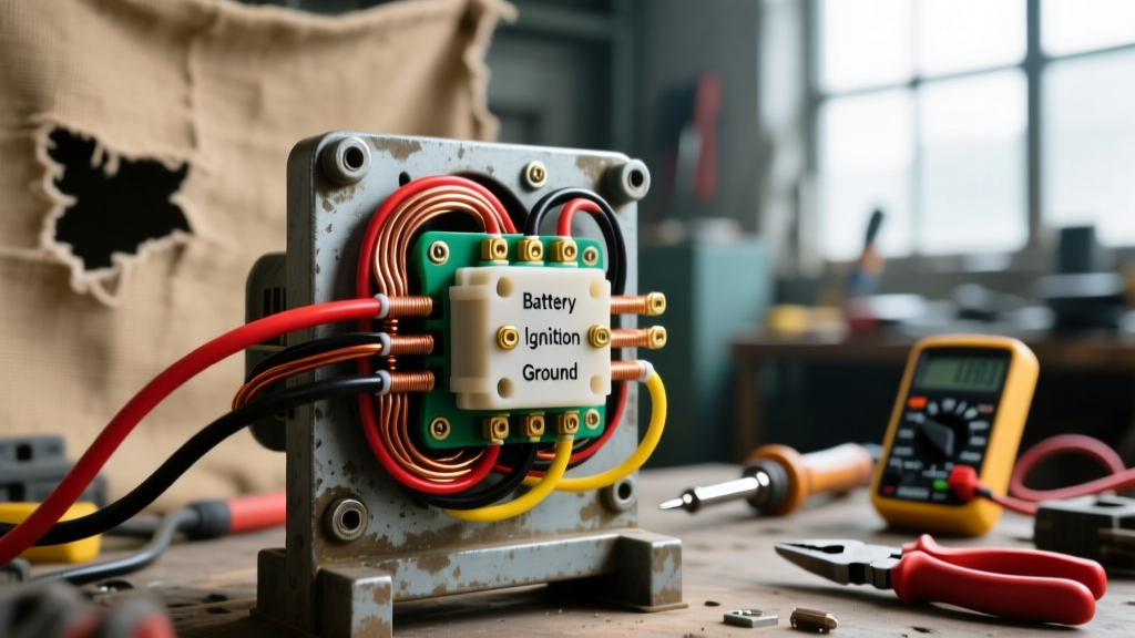
Most lawn mower ignition switches adhere to the Society of Automotive Engineers (SAE) standard for terminal lettering. Before you disconnect a single wire, you must understand what each letter represents. The most common mistake DIYers make is assuming wire colors are universal across brands like John Deere, Cub Cadet, and Craftsman. They are not. Always wire by the terminal letter, not the wire color.
| Terminal Letter | Function | Typical Wire Gauge | Continuity State (RUN) | Continuity State (OFF) |
|---|---|---|---|---|
| B | Battery (12V+ Input) | 10 AWG or 12 AWG | Source Power | Source Power |
| L | Lights / Accessories | 14 AWG or 16 AWG | Connected to B | Open |
| A | Alternator / Armature | 14 AWG | Connected to B | Open |
| S | Starter Solenoid | 10 AWG or 12 AWG | Open | Open |
| M | Magneto (Kill Circuit) | 14 AWG or 18 AWG | Open | Connected to G |
| G | Ground | 12 AWG | Grounded | Connected to M |
The Critical Divide: Magneto vs. Battery Ignition Systems
You cannot use a battery-ignition switch on a magneto-ignition engine without risking catastrophic electrical damage or a failure to shut off the engine. Briggs & Stratton Support documentation heavily emphasizes verifying your engine's ignition type before ordering a replacement switch.
Magneto Ignition (Standard on 90% of Riding Mowers)
In a magneto system, the engine generates its own spark via a flywheel and coil. To kill the engine, the ignition switch must ground the magneto wire. In the OFF position, the switch internally bridges the M (Magneto) and G (Ground) terminals. If you install a switch lacking the M terminal, the mower will run indefinitely, forcing you to stall it via the PTO or choke.
Battery Ignition (Common on Older Tractors & Commercial Models)
Battery ignition systems rely on the 12V battery to power the ignition coil. To kill the engine, the switch must cut power to the coil. These switches do not use an M terminal; instead, they interrupt the B-to-A or B-to-Coil circuit. Installing a magneto switch on a battery system will result in a dead short to ground the moment you turn the key off, potentially blowing your main fuse or damaging the stator.
2026 Upgrade Options: Beyond the OEM Plastic Switch
Original Equipment Manufacturer (OEM) switches are typically constructed with basic plastic housings and open-back terminals. For mowers stored outdoors or used in commercial landscaping, upgrading to a sealed switch is highly recommended.
- Oregon 33-415 (Universal 5-Pin): Priced around $14-$18, this is the standard direct-fit replacement for most Craftsman and Husqvarna magneto systems. It features a basic rubber O-ring seal.
- Stens 430-854 (Heavy-Duty 6-Pin): Retailing for $28-$35, this upgrade features an IP65-rated weather seal, a ceramic internal wafer to resist arcing, and a metal mounting nut. Ideal for commercial zero-turn mowers exposed to daily pressure washing.
- Rotary 19848 (Marine-Grade): Costing roughly $42, this switch includes a rubber boot over the key cylinder and sealed, epoxy-filled terminal backs to completely block moisture and fertilizer-induced corrosion.
Step-by-Step Replacement and Wiring Procedure
Follow this precise workflow to ensure a safe installation. You will need a digital multimeter (such as the Klein Tools MM400), a 5/8-inch or 3/4-inch deep socket, and wire brush cleaner.
- Isolate the Power: Disconnect the negative (black) battery cable first, followed by the positive. This prevents accidental shorting if your wrench bridges the B-terminal to the mower frame.
- Document the OEM Harness: Before pulling any spade connectors, take a high-resolution photograph of the back of the old switch. Do not rely on memory or wire color alone.
- Remove the Retaining Hardware: Unscrew the face nut. If the switch spins freely, use needle-nose pliers to hold the anti-rotation tab located at the 12 o'clock position.
- Prep the Terminals: Use a fiberglass scratch pen to clean oxidation off the female spade connectors on the mower's wiring harness. Apply a small dab of Permatex 22058 Dielectric Grease to each connector to prevent future galvanic corrosion.
- Map and Connect: Push the connectors onto the new switch according to your photograph and the SAE lettering stamped into the plastic housing. Ensure each connector 'clicks' into the detent.
- Pre-Flight Continuity Test: Before reconnecting the battery, use your multimeter in continuity mode (beep setting) to verify the switch logic.
Pro-Tip: Always test the 'M' to 'G' continuity in the OFF position. If your multimeter does not beep when the key is off, the mower will not shut down. Do not reconnect the battery until this specific circuit is verified.
Advanced Troubleshooting & Edge Cases
Even with the correct ignition switch wiring diagram for lawn mower applications, secondary issues can mimic a bad switch.
The Mower Cranks but Will Not Start
If the starter engages (meaning the B-to-S circuit is healthy) but the engine fails to fire, check the A (Alternator) terminal. On many modern mowers, the A terminal powers the fuel solenoid on the carburetor bowl. If the A terminal wire is loose, the fuel solenoid remains closed, starving the engine of gas despite a healthy spark.
Safety Interlock Interruptions
Modern mowers integrate the ignition switch 'S' (Starter) terminal with a series of safety relays (Seat Switch, PTO Switch, Brake Pedal Switch). If you turn the key to START and hear only a faint click, the switch is likely fine. Instead, a safety interlock is preventing the 12V signal from reaching the starter solenoid. Bypassing these relays to force a start is a severe violation of OPEI safety guidelines and can result in the mower blades engaging while the operator is off the seat.
The 'Run-On' or Dieseling Effect
If the ignition switch tests perfectly (M and G bridge correctly in the OFF position), but the engine still sputters and runs for 5 to 10 seconds after turning the key, you are experiencing 'dieseling.' This is not an electrical fault. It occurs when carbon buildup in the combustion chamber ignites raw fuel without a spark. The fix is mechanical: use a fuel system cleaner, replace the spark plug, and ensure the carburetor fuel solenoid is snapping shut instantly when power is cut.
Final Torque and Reassembly Specifications
When reinstalling the dash panel, ensure the ignition switch face nut is torqued to exactly 15 to 20 inch-pounds. Overtightening the plastic or metal nut will crack the switch housing or strip the internal wafer alignment, causing the key to bind in the START position. If your upgrade includes a rubber weather boot, ensure the drain hole at the 6 o'clock position on the boot is left unobstructed to allow condensation to escape.
By strictly adhering to the SAE terminal designations and verifying continuity prior to applying battery power, you ensure your mower's electrical system remains safe, reliable, and ready for the demands of the 2026 mowing season.