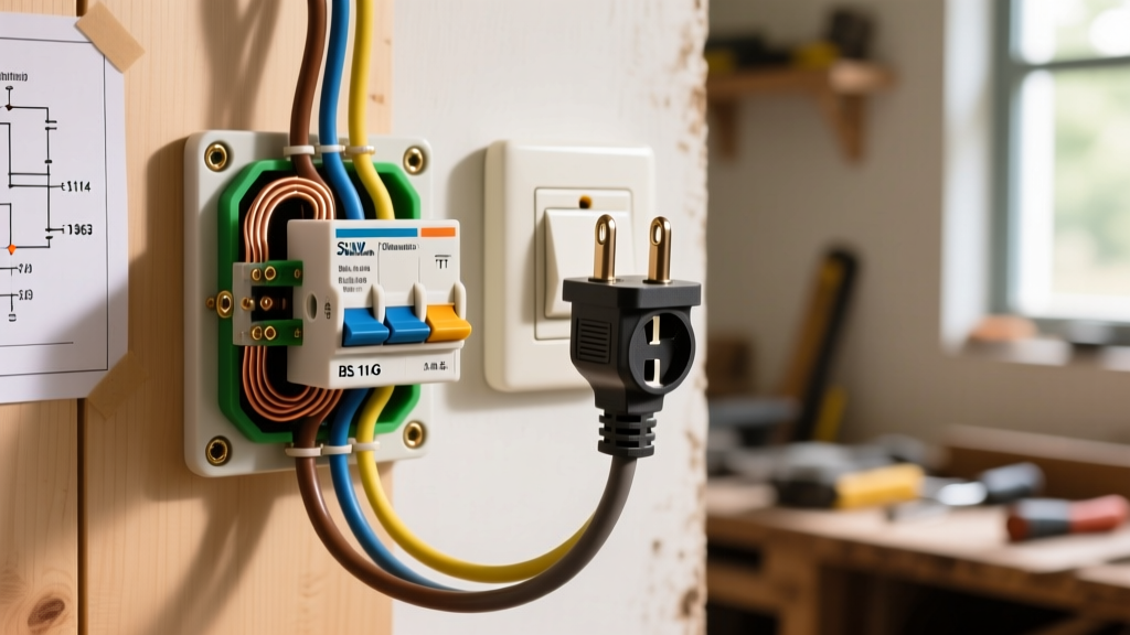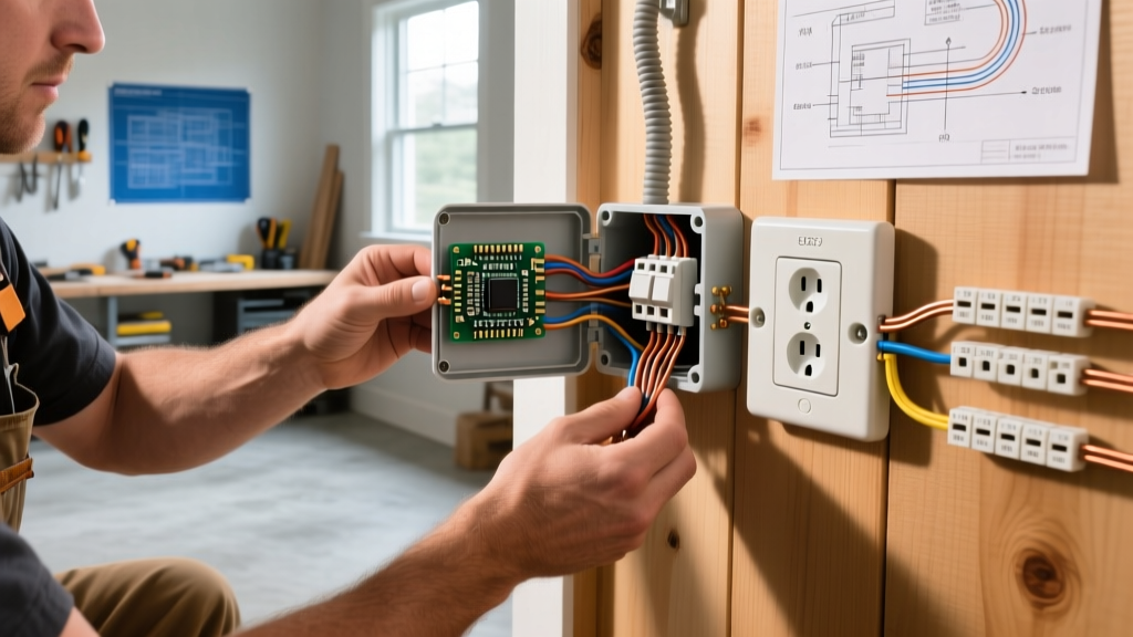

The Critical Role of Switch Circuit Inspection
When troubleshooting or verifying electrical wiring for light switch installations, relying solely on a simple flip of the toggle is a recipe for hidden hazards. Arc faults, loose neutrals, and overloaded junction boxes often remain invisible until they cause thermal damage or fire. As of the 2026 NEC adoption cycle, inspectors and master electricians emphasize rigorous multi-stage testing protocols to ensure long-term reliability and safety.
This comprehensive inspection guide transitions from de-energized visual checks to live voltage verification and advanced thermal imaging. Whether you are verifying a new single-pole installation or diagnosing a complex 4-way traveler circuit, these methodologies will ensure your electrical wiring for light switch setups meets the highest safety standards.
Phase 1: Pre-Test Safety & Tool Calibration
Before opening any junction box, establish a strict Lockout/Tagout (LOTO) procedure. Verify the absence of voltage using a Category III or IV rated Non-Contact Voltage Tester (NCVT), such as the Klein Tools NCVT-3, followed by a live-dead-live test on a known voltage source using a True-RMS digital multimeter like the Fluke 117.
Expert Warning: Never trust a single NCVT reading. Capacitive coupling in multi-gang boxes can induce "phantom voltage" on de-energized wires, leading to false positives. Always confirm with a direct-contact multimeter before touching conductors. For more on proper meter usage, refer to the Fluke guide on digital multimeters.
Phase 2: Visual & Mechanical Inspection (De-Energized)
Once the circuit is confirmed dead and the switch is removed from the box, conduct a meticulous physical inspection of the electrical wiring for light switch terminations and box capacity.
1. NEC Box Fill Calculations (Article 314.16)
Overcrowded boxes cause insulation damage and trap heat. Calculate the box fill based on the largest conductor present. For standard 14 AWG copper wire, each conductor counts as 2.0 cubic inches. The device (switch) counts as two conductor volumes (4.0 cu in). All grounding conductors combined count as one volume (2.0 cu in), and internal clamps count as one volume.
- Standard Single-Gang Plastic Box: Typically 18 to 22 cubic inches.
- Deep Single-Gang Box: 22.5+ cubic inches (recommended for smart switches or dimmers with large heat sinks).
2. Conductor Preparation & Strip Length
Inspect the exposed copper. If the wire was stripped too far, bare copper will be visible past the terminal pad, creating a shock hazard and short-circuit risk. If stripped too short, the insulation may be pinched under the terminal screw, resulting in a high-resistance connection.
- 14 AWG Solid Copper: Requires exactly 5/8-inch strip length for standard side-wiring.
- 12 AWG Solid Copper: Requires 3/4-inch strip length.
3. Terminal Torque & Backstab Failures
Push-in "backstab" terminals (common on builder-grade $1 switches) rely on spring tension that frequently relaxes under continuous 15A loads, leading to arcing. Always inspect for scorch marks around backstab holes. For side-wiring, terminal screws must be torqued to manufacturer specifications. For example, Leviton specifies 12 to 14 in-lbs for their standard Decora switch terminal screws. Under-torquing causes micro-arcing; over-torquing strips the brass threads or fractures the wire.
Phase 3: Continuity & Resistance Testing (De-Energized)
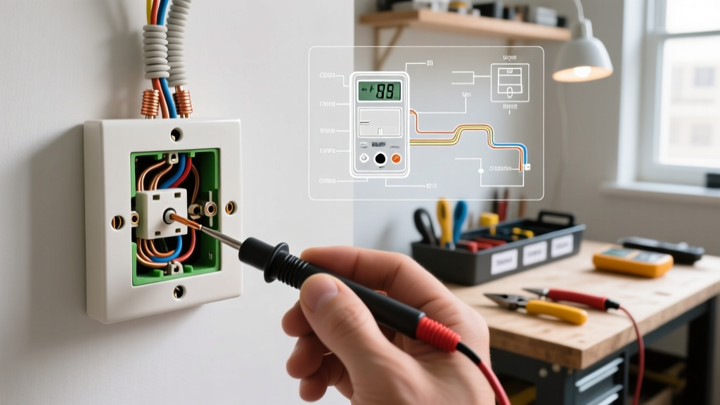
With the power locked out, set your multimeter to the Continuity (diode symbol) or Ohms (Ω) setting to test the switch mechanics and wire integrity.
Testing Single-Pole Switches
- Place one probe on the brass line terminal and the other on the load terminal.
- Toggle the switch ON: The meter should read near 0.00Ω and emit a continuous beep.
- Toggle the switch OFF: The meter should read "OL" (Open Line) or infinite resistance.
- Edge Case: If you read fluctuating resistance (e.g., jumping between 2Ω and 15Ω) while the switch is ON, the internal carbon contacts are pitted and the switch must be replaced.
Testing 3-Way Switch Travelers
Diagnosing the electrical wiring for light switch setups involving 3-way circuits requires mapping the travelers. A standard 3-way switch (like the Leviton 5603-2W) has one Common (dark screw) and two Travelers (brass screws).
- Place Probe A on the Common screw.
- Place Probe B on Traveler 1. Toggle the switch. Note if continuity is made or broken.
- Move Probe B to Traveler 2. Toggle the switch. The continuity state must be the exact opposite of Traveler 1.
- If both travelers show continuity simultaneously, or neither shows continuity, the internal toggle mechanism has failed.
Phase 4: Live Voltage & Polarity Verification (Energized)
Restore power to the circuit to verify line/load orientation and check for voltage drops. For advanced diagnostics, consult the NFPA 70 National Electrical Code regarding proper grounding and switching of ungrounded conductors (NEC 404.2).
Identifying Line vs. Load in Single-Gang Boxes
In older homes, both the line (power from panel) and load (power to fixture) wires may enter the same switch box, often both colored black. To identify them safely:
- Set the multimeter to AC Voltage (V~).
- Carefully measure between the bare copper ground wire and each black wire.
- The wire reading ~120V (or ~230V in EU/UK regions) is the Line.
- The wire reading 0V (or phantom voltage around 30-50V) is the Load.
Note: Smart switches and WiFi dimmers (like the Lutron Caseta series) require absolute line/load identification to prevent frying the internal logic board.
Diagnostic Matrix: Multimeter Readings & Faults
Use this reference table to quickly diagnose anomalies found during live testing of your electrical wiring for light switch circuits.
| Test Scenario | Expected Reading | Anomalous Reading | Probable Fault / Edge Case |
|---|---|---|---|
| Line to Ground | 120V AC | 105V - 112V AC | Voltage drop due to undersized wire, long run (>100ft), or loose neutral at the panel. |
| Load to Ground (Switch OFF) | 0V AC | 40V - 90V AC | Phantom voltage from capacitive coupling in multi-conductor cables (Romex). Use True-RMS meter to filter. |
| Neutral to Ground | < 2V AC | > 5V AC | Shared neutral overload, loose neutral bus bar, or illegal neutral-ground bond downstream. |
| Switch Continuity (ON) | 0.0Ω - 0.5Ω | 15Ω - 50Ω | Severe internal contact degradation; imminent thermal failure. |
Phase 5: Infrared Thermography for Loose Connections
Visual inspections cannot see resistance heating. Under a sustained load (e.g., multiple recessed LED cans or a heavy incandescent chandelier), loose terminal screws generate heat. Using a thermal imaging camera like the FLIR TG267, scan the switch faceplate and exposed terminals after the circuit has been under load for 15 minutes.
- Normal Delta T: The switch terminals should be within 2°F to 5°F of ambient room temperature.
- Warning Threshold: A Delta T (temperature difference) of 10°F to 15°F above ambient indicates a loosening screw or degrading backstab connection.
- Critical Failure: Any hotspot exceeding 140°F (60°C) or showing a Delta T > 25°F requires immediate de-energization and termination repair. For more on workplace electrical safety and hazard mitigation, review the OSHA Electrical Safety Standards.
Expert Troubleshooting Flowchart: Flickering & Dimming Issues
When the electrical wiring for light switch setups results in flickering or ghost-glowing (especially with LED fixtures), follow this diagnostic sequence:
- Check for Illuminated Switches: Switches with built-in neon locators leak a small trickle current (1-2mA) to power the neon bulb. This current can charge the capacitor in LED drivers, causing a strobe effect. Fix: Replace with a standard toggle or install a bypass resistor at the fixture.
- Verify Dimmer Compatibility: If using a TRIAC-based dimmer on an LED circuit, ensure the dimmer is ELV (Electronic Low Voltage) or MLV compatible. Standard incandescent dimmers chop the AC sine wave incorrectly for LED drivers, causing audible buzzing and flickering.
- Inspect the Neutral: Smart switches require a dedicated neutral. If the neutral wire is sharing a loose wire nut with multiple other circuits, the smart switch will reboot randomly, causing the lights to flash.
Final Sign-Off
Properly inspecting and testing electrical wiring for light switch circuits requires moving beyond basic functionality checks. By combining NEC box-fill calculations, precise mechanical torque verification, True-RMS voltage testing, and thermal imaging, you ensure the installation is not just operational, but inherently safe for decades of use. Always document your baseline voltage and thermal readings for future maintenance comparisons.