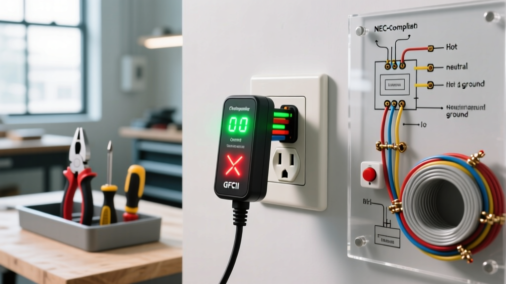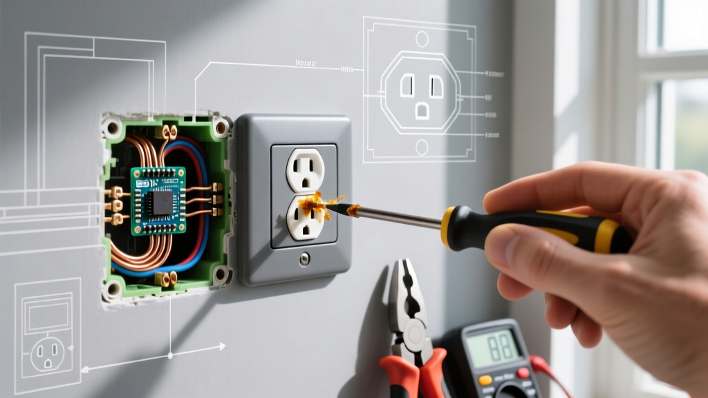

The Physics Behind an Electrical Outlet Hot to Touch
A standard 15-amp or 20-amp residential receptacle should never exceed ambient room temperature by more than a few degrees. When an electrical outlet is hot to touch—typically registering above 100°F (38°C) on the faceplate or yoke—it indicates high electrical resistance at the termination points. This resistance converts electrical current into thermal energy (heat) following Joule's first law. In 2026, with the continuous load demands of modern high-wattage appliances, space heaters, and window AC units, marginal connections degrade rapidly.
The most common culprit in residential wiring is the use of 'backstabbed' push-in terminals on cheap, builder-grade receptacles. These spring-loaded contacts grip the wire with minimal surface area, leading to micro-arcing, oxidation, and eventual thermal runaway. To fix this, we must abandon the backstab method and perform a proper step-by-step installation using a commercial-grade, side-wired receptacle.
Diagnostic Matrix: Identifying the Heat Source
Before beginning the installation, use an infrared thermometer to map the heat signature. This helps identify the exact failure mode.
| Heat Location | Probable Cause | Failure Mode & Edge Case |
|---|---|---|
| Rear Plastic Housing | Backstabbed Push-In Terminals | Spring tension loss over time; high resistance under continuous 12A+ loads. |
| Brass Strap / Side Screws | Loose Terminal Screws | Thermal expansion/contraction cycles loosen the screw, causing micro-arcing. |
| Entire Faceplate / Wall | Circuit Overload | Drawing 1800W+ on a 15A circuit with 14 AWG wire causing whole-wire heating. |
| Wire Insulation Only | Aluminum Wiring Oxidation | Galvanic corrosion at copper-aluminum junctions creating massive resistance. |
Required Tools and Materials for Safe Replacement
Do not attempt this installation with subpar tools. Precision and verified de-energization are mandatory.
- Fluke 117 True-RMS Multimeter (~$190): Essential for non-contact voltage verification and testing continuity.
- Klein Tools 11055 Wire Stripper (~$25): For cleanly stripping 14 and 12 AWG solid copper without nicking the conductor.
- Leviton 5262-SW Commercial Grade Receptacle (~$3.50): Features a thick brass strap and deep side-wire wells. Do not use standard $1.25 residential models.
- Wago 221-412 Lever Nuts (~$0.40 each): For secure, low-resistance pigtailing if the existing wires are too short.
- CDI 1002MRMH Torque Screwdriver (~$110): Required to meet NEC 110.14(D) termination torque specifications.
Step-by-Step Installation: Replacing the Hazardous Outlet
Step 1: Lockout/Tagout (LOTO) and Verification
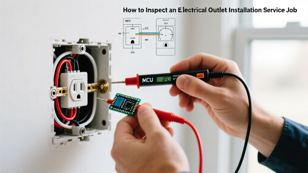
Navigate to your main electrical panel and switch off the breaker controlling the suspect outlet. For maximum safety, apply a physical lockout tag to the breaker panel so no one accidentally flips it while you are working. Insert your Fluke 117 probes into the top and bottom slots (Line to Neutral, Line to Ground) to verify 0.0V. Test a known live outlet first to confirm your multimeter is functioning correctly.
Step 2: Extraction and Annealing Inspection
Remove the center screw and pull the faceplate off. Unscrew the top and bottom yoke mounting screws and gently pull the hot receptacle from the gang box. Critical Inspection: Examine the exposed copper wire. If the copper appears dark, dull, or snaps easily when bent, it has undergone thermal annealing due to prolonged heat exposure. Annealed copper loses its structural integrity and conductivity. You must use your Klein strippers to cut back the wire until you reach shiny, flexible, unoxidized copper—usually requiring you to snip off at least 1 inch of damaged conductor.
Step 3: Pigtailing for Box Capacity
If cutting back the annealed wire leaves you with less than 6 inches of free conductor length inside the box (a strict NEC violation), you must pigtail. Strip 1/2 inch of insulation from the existing wire and a new 14 AWG (or 12 AWG, matching the circuit) THHN copper pigtail. Insert both into a Wago 221 lever nut and snap the levers down. Wago connectors provide a gas-tight, vibration-proof connection that will never loosen or generate heat, unlike twisted wire nuts which can fail if under-torqued.
Step 4: Side-Wiring the Commercial Receptacle
Take your Leviton 5262-SW receptacle. Strip exactly 5/8 inch of insulation from your pigtails or existing wires using the precise gauge hole on your wire strippers. Form a 'shepherd's hook' with the needle-nose pliers. Crucial Technique: Loop the hook clockwise around the brass (hot) and silver (neutral) terminal screws. When you tighten the screw, the clockwise motion pulls the wire loop tighter into the well. If you loop counter-clockwise, the screw will push the wire out, creating a high-resistance hot spot. Ensure no bare copper is visible outside the terminal well, and no insulation is trapped under the screw head.
Step 5: Torque and Reinstallation
Modern electrical codes strictly enforce termination torque to prevent the exact 'hot to touch' scenario we are fixing. Set your torque screwdriver to the manufacturer's specification (typically 12 to 14 in-lbs for 14/12 AWG wire on Leviton commercial devices). Tighten the terminal screws until the torque driver clicks. Connect the bare/green ground wire to the green grounding screw using the same clockwise loop and torque method. Carefully fold the wires into the back of the gang box using a 'Z-fold' pattern to avoid pinching the conductors against the metal box edges. Secure the yoke with the provided 6-32 mounting screws.
Step 6: Post-Installation Testing and Thermal Monitoring
Restore power at the breaker panel. Use your multimeter to verify 120V (+/- 5%) across the hot and neutral slots. Plug in a standard 1500W space heater or high-draw appliance to simulate a continuous heavy load. Let it run for 20 minutes. Use an infrared thermometer to scan the new faceplate. The temperature should remain within 5°F of the ambient room temperature. If the Consumer Product Safety Commission (CPSC) guidelines on electrical safety are met, your installation is a success.
Frequently Asked Questions (FAQ)
Can I just tighten the screws on my existing hot outlet instead of replacing it?
No. Once an outlet has generated enough heat to become noticeably hot to touch, the internal brass straps have likely warped, and the spring tension in the contacts is permanently compromised. Tightening the screws is a temporary band-aid that will inevitably lead to arcing and potential ignition. Complete replacement is the only safe protocol.
Is it normal for a dimmer switch or smart outlet to feel warm?
Yes, but with caveats. Solid-state devices like smart receptacles (e.g., Leviton DW15R) or dimmer switches contain internal TRIACs and power supplies that dissipate a small amount of heat. They may feel 'warm' (up to 120°F) to the touch. However, a standard passive duplex receptacle has no internal electronics; any heat is purely resistive and indicates a dangerous failure.
What if my home has aluminum wiring and the outlet is hot?
Aluminum wiring expands and contracts at a different rate than copper, causing terminal screws to loosen over time, leading to severe heating. If you discover dark gray, oxidized aluminum wires, do not connect them directly to a standard copper-rated receptacle. You must use CO/ALR rated devices or, preferably, pigtail the aluminum to copper using AMP COPALUM crimps or King Innovation Alumiconn lug connectors before installing the new receptacle. For more on code compliance, refer to the National Electrical Code (NEC) guidelines on aluminum terminations.