
Why Post-Installation Verification is Non-Negotiable
Wiring a new 15-amp or 20-amp receptacle is only half the job. According to the National Fire Protection Association (NFPA), electrical failures or malfunctions remain a leading cause of structural fires. When you install a new outlet, verifying correct polarity, proper grounding, and secure termination is critical. Learning how to properly test an electrical outlet ensures your installation meets National Electrical Code (NEC) standards, prevents shock hazards, and protects downstream electronics from catastrophic surge damage or improper return paths.
⚠️ CRITICAL SAFETY WARNING: Never assume a circuit is dead based solely on a wall switch or a cheap non-contact voltage tester. Always verify zero energy with a calibrated True-RMS multimeter before touching bare conductors. Refer to OSHA electrical safety guidelines for proper Lockout/Tagout (LOTO) procedures when working on live panels or verifying initial terminations.Diagnostic Tool Matrix: Choosing the Right Tester
To thoroughly test an electrical outlet, you need the right diagnostic equipment. Relying on a single tool can leave hidden faults undetected. Below is a comparison of the primary testing tools used by professional electricians in 2026.
| Tool Type | Recommended Model | Approx. Cost | Best Use Case | Limitations |
|---|---|---|---|---|
| 3-Light Receptacle Tester | Klein Tools RT250 | $28 | Quick polarity, GFCI trip, and basic ground verification. | Cannot detect bootleg grounds or high-impedance neutrals. |
| True-RMS Multimeter | Fluke 117 | $220 | Exact voltage measurement, checking voltage drop, verifying true ground. | Requires manual probe placement; slower than plug-in testers. |
| Advanced Circuit Analyzer | Amprobe AT-3500 | $350 | Measures ground impedance, line impedance, and AFCI/GFCI trip times. | Expensive; overkill for basic residential DIY swaps. |
Phase 1: Pre-Power Mechanical & Visual Inspection
Before you turn the breaker back on to test an electrical outlet, you must perform a mechanical inspection. The Consumer Product Safety Commission (CPSC) frequently highlights loose terminations as a primary cause of residential arc faults.
1. Eliminate Back-Stabbed Connections
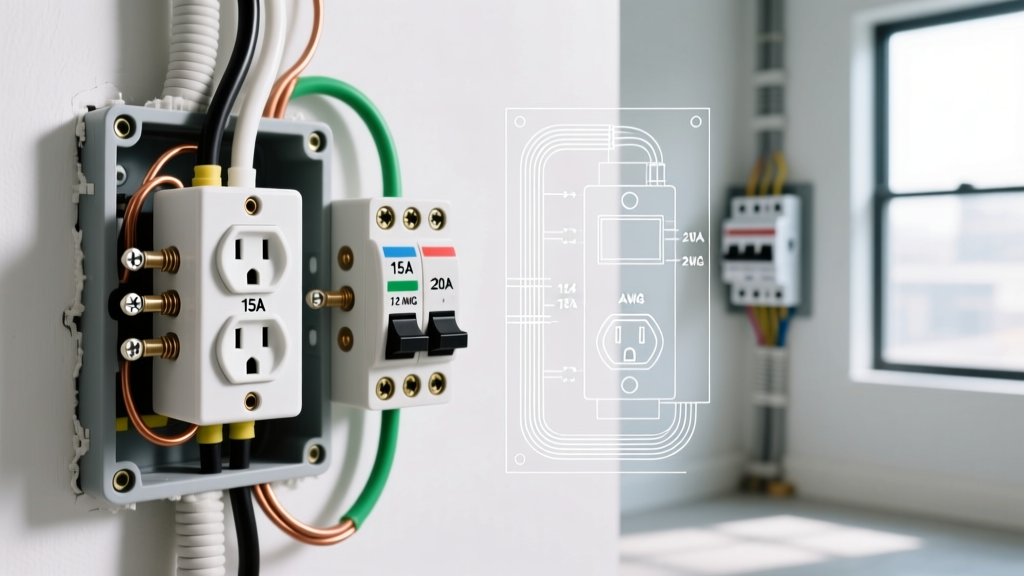
Never use the push-in (back-stab) terminals on standard 15A or 20A receptacles. These rely on spring-loaded metal grips that loosen over time due to thermal expansion and contraction (thermal cycling). Always use the side-screw terminals or the internal screw-to-clamp plates found on premium commercial-grade receptacles (like the Leviton 5362 or Eaton TR20W).
2. Verify Torque Specifications
The NEC now strictly mandates that terminations be torqued to the manufacturer's specifications. For most standard 14 AWG and 12 AWG copper wires on 15A/20A receptacles, the required torque is 14 in-lbs (inch-pounds). Use a calibrated torque screwdriver, such as the Milwaukee 48-22-9000, to ensure the screw is tight enough to prevent arcing, but not so tight that it strips the brass threads or shears the screw head.
3. Check Wire Wrap Direction
Ensure the wire loops around the terminal screw in a clockwise direction. When you tighten the screw, the loop should pull tighter around the shaft. A counter-clockwise wrap will push the wire out from under the screw head as torque is applied, creating a high-resistance connection.
Phase 2: How to Test an Electrical Outlet with a Receptacle Tester
Once the breaker is energized, the first step in live testing is using a 3-light receptacle tester. This provides an immediate baseline for the most common wiring errors.
- Insert the Tester: Plug the Klein Tools RT250 (or equivalent) firmly into the newly installed receptacle.
- Read the LED Matrix: Look at the three indicator lights. Two yellow lights typically indicate a correctly wired, grounded 120V circuit.
- Test GFCI Functionality: If the receptacle is a GFCI model (or downstream of one), press the black "GFCI Test" button on the tester. The receptacle should immediately trip with an audible click, cutting power to the tester. Reset the GFCI manually to restore power.
Note: While a 3-light tester is excellent for catching reversed hot/neutral wires or an entirely missing ground wire, it cannot verify the quality of the ground. This requires Phase 3.
Phase 3: Advanced Verification with a True-RMS Multimeter
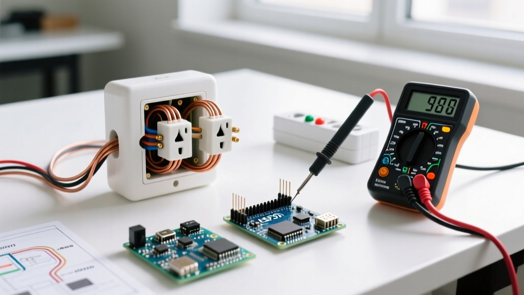
To truly certify the installation, you must test an electrical outlet using a digital multimeter (DMM). This confirms exact voltage levels and identifies high-resistance faults that plug-in testers miss.
Step-by-Step Multimeter Pinout Testing
Set your Fluke 117 (or similar True-RMS DMM) to AC Voltage (V~). Insert the black probe into the COM jack and the red probe into the V/Ω jack.
- Test 1: Hot to Neutral (Line to Load)
Insert the red probe into the short slot (Hot) and the black probe into the long slot (Neutral).
Expected Reading: 118V to 122V. If it reads significantly lower (e.g., 105V), you have a voltage drop issue or a loose neutral upstream. - Test 2: Hot to Ground (Line to Earth)
Insert the red probe into the short slot (Hot) and the black probe into the U-shaped ground hole.
Expected Reading: 118V to 122V. This confirms the ground path is bonded back to the panel and is capable of carrying fault current. - Test 3: Neutral to Ground (Load to Earth)
Insert the red probe into the long slot (Neutral) and the black probe into the U-shaped ground hole.
Expected Reading: 0.0V to 1.5V. Critical: If this reads >2.0V, your neutral wire is loose, undersized, or overloaded, causing a dangerous voltage gradient on the grounding system.
Troubleshooting Common Wiring Faults
When you test an electrical outlet and receive abnormal readings, use this diagnostic matrix to identify and correct the fault.
| Fault Condition | 3-Light Tester Indication | Multimeter (Hot-Gnd) | Root Cause & Required Fix |
|---|---|---|---|
| Open Ground | Left Yellow, Right Red (varies by brand) | 0V or Floating | Ground wire disconnected at receptacle or panel. Re-terminate bare copper to green screw. |
| Reversed Polarity | Right Yellow Only | 120V (but on Neutral slot) | Hot and Neutral swapped. Move black wire to brass screw, white wire to silver screw. |
| Open Neutral | No Lights / Center Red | 120V (Hot-Gnd), 0V (Hot-Neu) | Neutral wire loose or broken upstream. Check wire nuts and silver terminal screw. |
| Hot/Ground Reversed | All Lights Off or Error Code | 0V (Hot-Gnd), 120V (Neu-Gnd) | Extremely dangerous. Panel breaker may not trip on fault. Immediately correct wire mapping. |
Edge Cases: The "Bootleg Ground" and Shared Neutrals
One of the most deceptive faults you can encounter when you test an electrical outlet in an older home (or after a sloppy DIY renovation) is the bootleg ground. This occurs when a previous installer places a small jumper wire between the neutral (silver) terminal and the ground (green) terminal on the receptacle to trick a 3-light tester into showing a "correct" wiring pattern.
How to Detect a Bootleg Ground
A standard 3-light tester will read a bootleg ground as perfectly fine. However, this is a severe shock hazard; if the neutral wire ever disconnects upstream, the metal chassis of any plugged-in appliance will become energized at 120V. To detect this without removing the faceplate:
- Set your multimeter to AC Voltage.
- Measure Hot to Neutral (should be ~120V).
- Measure Hot to Ground (should be ~120V).
- Turn off the breaker controlling the circuit.
- Set the multimeter to Continuity (Ohms/Beep).
- Measure between the Neutral slot and the Ground hole. If you get a dead short (near 0.0 ohms) with the power off, you have a bootleg ground or an improper neutral-to-ground bond at the receptacle. The NEC strictly prohibits bonding neutral and ground anywhere downstream of the main service panel.
Final Commissioning Steps
Once your multimeter and receptacle tester confirm correct polarity, a solid ground path, and proper voltage levels, your final step is mechanical securing. Ensure the receptacle yoke sits flush against the drywall. If the electrical box is recessed more than 1/4 inch from the finished wall surface, NEC code requires the use of plastic box extenders (spacers) to prevent arc flashes from escaping into the wall cavity. Install the faceplate, torque the 6-32 faceplate screw to roughly 6 in-lbs to avoid cracking the cover, and your installation is fully commissioned and safe for use.