
The Visual Language of Receptacle Wiring
Understanding how to read and interpret electrical schematics is the foundational skill for any DIYer or apprentice electrician. When installing an electrical outlet, a wiring diagram is not merely a suggestion; it is a precise map of current flow, grounding paths, and overcurrent protection. In 2026, with the widespread adoption of the latest National Electrical Code (NEC) cycles across most US municipalities, misinterpreting a diagram can lead to immediate inspection failures or severe arc-fault hazards.
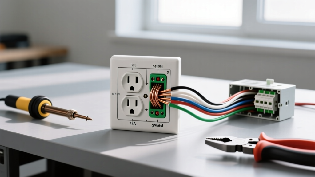
At its core, a standard receptacle wiring diagram abstracts physical reality into standardized symbols. The 'ungrounded' conductor (hot) is universally depicted in black or red, the 'grounded' conductor (neutral) in white or gray, and the 'equipment grounding conductor' (EGC) in bare copper or green. However, diagrams also illustrate spatial relationships—such as the difference between a series and parallel daisy-chain—which dictate how downstream devices behave if an upstream connection fails.
15-Amp vs. 20-Amp Circuit Diagram Specifications
One of the most common errors when installing an electrical outlet is mismatching the receptacle rating to the branch circuit breaker. A wiring diagram will explicitly state the overcurrent protection device (OCPD) size. Below is a technical comparison of the two most common residential branch circuits.
| Feature | 15-Amp Standard Circuit | 20-Amp Standard Circuit |
|---|---|---|
| Breaker Size | 15A Single-Pole | 20A Single-Pole |
| Wire Gauge (Copper) | 14 AWG | 12 AWG |
| Receptacle Model Example | Leviton 5262-W (15A Duplex) | Leviton 5362-W (20A Duplex) |
| Average 2026 Retail Cost | $1.25 - $1.75 | $4.15 - $5.50 (Commercial Grade) |
| Terminal Screw Torque | 14 in-lbs | 14 in-lbs |
| NEC Receptacle Rule | Can be used on 15A or 20A circuits | Required if a single receptacle is on a 20A circuit |
Notice the torque specification. Modern diagrams and manufacturer spec sheets mandate specific torque values. Using a calibrated screwdriver to achieve exactly 14 inch-pounds on the brass and silver terminal screws prevents thermal expansion loosening over time, a leading cause of residential electrical fires.
Step-by-Step Translation: Installing an Electrical Outlet
Translating a 2D schematic into a 3D physical termination requires strict adherence to mechanical best practices. Follow this sequence when executing the diagram in the field:
- De-energize and Verify: Turn off the breaker and use a non-contact voltage tester (NCVT) followed by a multimeter to confirm 0V between hot-to-neutral and hot-to-ground. Always follow OSHA electrical safety guidelines regarding lockout/tagout procedures, even in residential settings.
- Conductor Preparation: Strip exactly 3/4 inch of insulation from the 14 AWG or 12 AWG solid copper conductors. Stripping too little results in insulation binding under the screw head; stripping too much leaves exposed bare wire, creating a shock hazard.
- Form the Shepherd's Hook: Use needle-nose pliers to bend the stripped wire into a tight, 180-degree U-shape. The loop must be perfectly round to maximize contact area under the terminal screw head.
- Terminate Clockwise: Hook the wire around the brass (hot) and silver (neutral) screws in a clockwise direction. This ensures that as the screw tightens, it pulls the loop tighter rather than pushing it out.
- Grounding: Terminate the bare/green EGC to the green grounding screw. If the outlet is housed in a metal junction box, a grounding pigtail must also connect the box to the receptacle's ground terminal.
Advanced Schematics: GFCI Line vs. Load
When a wiring diagram includes a Ground Fault Circuit Interrupter (GFCI), the complexity increases significantly. Standard duplex receptacles are bidirectional—power can enter either the top or bottom set of terminals. GFCI receptacles are strictly unidirectional.
A GFCI diagram will clearly demarcate the LINE and LOAD terminals. The LINE terminals receive incoming power directly from the breaker panel. The LOAD terminals feed power to downstream standard receptacles, extending the ground-fault protection to those devices. Swapping Line and Load is a critical failure mode. If reversed, the GFCI will still power the device plugged directly into it, but it will fail to trip during a ground fault, and downstream outlets will remain entirely dead. In 2026, most premium GFCI models feature internal line/load reversal lockouts that physically prevent the device from resetting if wired backward, but relying on this feature instead of reading the diagram is poor practice.
Multi-Wire Branch Circuits (MWBC) Diagram Logic
An MWBC diagram depicts two hot conductors (typically black and red), one shared neutral (white), and one ground, all originating from a single 3-wire cable (e.g., 14/3 or 12/3 NM-B). The two hot wires are connected to separate breakers on opposite phases (legs) of the panel, meaning the shared neutral only carries the unbalanced load, preventing neutral overload.
When installing an electrical outlet on an MWBC, the diagram will show a 'break-off' tab on the brass (hot) side of a duplex receptacle. This tab must be removed with pliers so the top outlet is fed by the black wire and the bottom outlet by the red wire. Crucially, the silver (neutral) tab must remain intact. Furthermore, NEC Article 210.4 mandates that the two breakers feeding this circuit must have a simultaneous disconnect (achieved via a handle tie or a 2-pole breaker). Failing to identify an MWBC diagram and removing the neutral tab instead of the hot tab will result in a dead short across 240 volts, causing an immediate and violent breaker trip.
Common Diagram Misinterpretations and Failures
Even experienced DIYers make errors when rushing through installations. Here are the most frequent deviations from the wiring diagram reference:
- Backstabbing (Push-In Terminals): Many diagrams show wires wrapping around screws, but the physical receptacle has push-in holes on the back. While NEC permits push-in connections for 14 AWG wire on 15A receptacles, they rely on a small internal spring clip. Over time, thermal cycling causes these clips to lose tension, leading to high-resistance arcing. Always use the side-wire screw terminals shown in standard schematics.
- Reversed Polarity: Connecting the black hot wire to the silver screw and the white neutral to the brass screw. The outlet will function, but the internal fuse of a plugged-in appliance will no longer be the first point of disconnect in a short circuit, and the outer shell of a lamp socket will become energized.
- Daisy-Chaining Grounds Improperly: When wiring multiple outlets in a series, the diagram shows the ground wires spliced together with a pigtail to the receptacle. Cutting the ground wire and simply jumping it from one green screw to the next means that if the first receptacle is removed, the downstream outlets lose their safety ground.
Frequently Asked Questions (FAQ)
Can I use a 20-amp receptacle on a 15-amp circuit?
Yes. The NEC allows 20-amp rated receptacles (which feature the T-shaped neutral slot) to be installed on 15-amp circuits. However, it is generally considered a waste of money since the circuit breaker will still trip at 15 amps, and standard 15-amp plugs do not require the T-slot. Conversely, you cannot use a 15-amp receptacle as a single, solitary outlet on a 20-amp circuit.
Why does my wiring diagram show a white wire wrapped in black tape?
In switch loops or specific 240V configurations, a white wire is used as an ungrounded (hot) conductor. The diagram will indicate this by showing black electrical tape or black marker on the ends of the white wire. This is a NEC requirement to re-identify the wire so future electricians know it is carrying line voltage, not serving as a neutral return.
What happens if I don't torque the terminal screws to spec?
Under-torqued screws create a loose mechanical connection. As current flows, the high resistance generates heat. This heat expands the metal, loosening the screw further in a cycle called 'thermal ratcheting.' Eventually, this leads to arc faulting and potentially an electrical fire. Always use an insulated torque screwdriver set to the manufacturer's specification (usually 14 in-lbs for standard residential receptacles).