
Decoding the Modern 3-Wire Switch Loop
For decades, residential electricians relied on simple 2-wire switch loops to control lighting fixtures. However, the rapid proliferation of smart home technology, timers, and motion sensors fundamentally changed how we wire and test switch boxes. When consulting a 3 wire wiring diagram for light switch installations today, you are almost always looking at a modern, NEC-compliant switch loop utilizing 14/3 or 12/3 NM-B cable. This configuration provides an always-hot line, a switched load, and a dedicated neutral conductor required by the National Electrical Code (NEC) Section 404.2(C).
As an electrical inspector or advanced DIYer, understanding how to test and verify this specific 3-wire topology is critical. Miswired neutrals or open travelers can lead to catastrophic smart switch failures, LED ghosting, or severe shock hazards. This inspection guide provides a rigorous, step-by-step framework for testing 3-wire light switch circuits with precision.
Essential Diagnostic Arsenal for 2026 Standards
Before opening a single junction box, you must equip yourself with the right diagnostic tools. Relying solely on a non-contact voltage tester is insufficient for verifying neutral integrity or identifying phantom voltages on load wires.
- True-RMS Digital Multimeter: The Fluke 117 True RMS Multimeter (approx. $190) is the industry standard. Its True-RMS capability is non-negotiable when testing circuits with modern LED drivers, which distort the AC sine wave and cause average-responding meters to display inaccurate readings.
- Non-Contact Voltage Tester (NCVT): The Klein Tools NCVT-2 (approx. $35) offers dual-range detection (12-48V and 48-1000V), allowing you to verify the absence of voltage before touching bare copper.
- Pigtail Probes & Wago Connectors: Use Wago 221-3 Lever Nuts to safely create temporary testing pigtails. Stabbing multimeter probes directly into stranded wire or crowded wire nuts often leads to slipped probes and short circuits.
Anatomy of the 3-Wire Switch Configuration
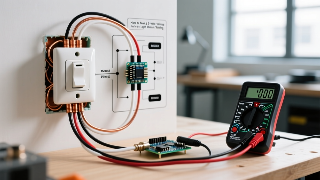
When analyzing a 3 wire wiring diagram for light switch circuits, the 14/3 or 12/3 Romex cable contains four physical wires: Black, Red, White, and Bare Copper. Here is how they are allocated in a standard single-pole smart-switch-ready loop:
1. The Black Wire (Line / Always Hot)
This conductor brings uninterrupted 120V power from the breaker panel to the switch box. It connects to the 'Line' or 'Hot' terminal on a smart switch. During testing, this wire should consistently read 120V relative to ground and neutral, regardless of the switch position.
2. The Red Wire (Load / Switched Hot)
This conductor carries the switched voltage up to the lighting fixture. It connects to the 'Load' terminal. Its voltage state is entirely dependent on the physical toggle of the switch or the internal relay of a smart module.
3. The White Wire (Neutral)
Mandated by the National Electrical Code to ensure smart switches have a complete 120V circuit to power their internal Wi-Fi/Zigbee radios. It connects to the 'Neutral' terminal and must be tied into the fixture's neutral return path at the ceiling box.
4. The Bare Copper (Equipment Ground)
Safety ground. Must be bonded to the metal switch box (if applicable) and the green ground screw on the switch yoke.
Voltage Testing Matrix: What to Expect
Use the following matrix when performing live-voltage testing at the switch box with the wires safely separated and capped, except for the specific points being probed. This data assumes a standard 120V residential AC system.
| Probe 1 (Red Lead) | Probe 2 (Black Lead) | Expected Voltage (Switch OFF) | Expected Voltage (Switch ON) | Diagnostic Meaning |
|---|---|---|---|---|
| Black (Line) | White (Neutral) | 120V | 120V | Confirms intact hot and neutral feed. |
| Black (Line) | Bare (Ground) | 120V | 120V | Confirms proper grounding bond. |
| Red (Load) | White (Neutral) | 0V | 120V | Verifies switch is successfully interrupting the hot leg. |
| Black (Line) | Red (Load) | 120V | 0V | Confirms potential difference across the switch contacts. |
| White (Neutral) | Bare (Ground) | < 2V | < 2V | Checks for neutral-to-ground faults or overloaded neutrals. |
Step-by-Step Diagnostic Protocol
Follow this rigorous procedure to inspect and test the circuit safely. Always adhere to OSHA electrical safety guidelines regarding lockout/tagout (LOTO) procedures before removing any device from the wall.
Phase 1: De-Energized Visual & Continuity Inspection
- LOTO the Breaker: Turn off the circuit breaker and apply a physical lockout tag. Verify zero energy using your NCVT on a known live source, then on the target switch wires.
- Sheath Inspection: Verify that the outer NM-B cable sheath extends at least 1/4 inch inside the electrical box. Exposed individual conductors outside the box are a Code violation and prone to physical damage.
- Continuity Test: Set your multimeter to the continuity (beep) setting. With the switch removed, test between the bare ground wire and the metal box. A continuous beep confirms the box is properly bonded.
Phase 2: Energized Voltage Verification
- Restore Power: Remove LOTO and energize the circuit. Keep all bare wire ends separated and capped with Wago lever nuts for safety.
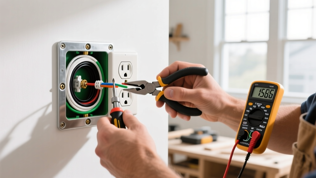
- Establish Reference: Insert the black (common) probe of your multimeter into the bare ground wire bundle. Use the red probe to verify 120V on the Black wire. This confirms your ground reference is solid.
- Verify the Neutral: Move the red probe to the White wire. You must read 120V between Black and White. If you read 0V here, but 120V between Black and Ground, you have an open neutral. This is the #1 reason smart switches fail to power on in newer homes.
- Test the Load Switching: Move the red probe to the Red wire. Toggle the mechanical switch (if testing a traditional setup) or wire nut the Black and Red wires together temporarily to simulate a closed relay. Verify the voltage transitions from 0V to 120V against the White neutral.
Inspector's Warning: Phantom Voltage on Load Wires
When testing the Red load wire against ground with the switch OFF, your True-RMS multimeter might display a reading between 20V and 60V. This is phantom voltage caused by capacitive coupling between the parallel conductors inside the 14/3 cable. To verify if it is phantom, switch your meter to the 'LoZ' (Low Impedance) setting if available, or place a 10k-ohm resistor across the probes. If the voltage drops to near zero, it is harmless phantom voltage. If it remains, you have a dangerous induced voltage or miswired circuit.
Advanced Edge Cases & Failure Modes
Even when the 3 wire wiring diagram for light switch setups is followed perfectly, modern components can introduce complex failure modes.
Edge Case 1: LED Ghosting and Flickering
Symptom: LED bulbs glow dimly when the switch is OFF, or flicker randomly.
Root Cause: Smart switches (like the Lutron Caseta PD-6ANS) draw a tiny amount of standby current (approx. 10mA) through the load wire to power their internal electronics, even when the relay is open. High-efficiency LEDs require very little current to illuminate, causing them to 'ghost'.
The Fix: Install a bypass capacitor (e.g., Lutron LUT-MLC, approx. $25) in parallel with the LED fixture at the ceiling box. This provides a high-impedance path for the standby current, bypassing the LED driver.
Edge Case 2: The Bootleg Neutral
Symptom: A smart switch powers on, but trips the GFCI breaker upstream, or causes a shock hazard.
Root Cause: An installer realized the neutral wire was missing or disconnected, so they improperly jumpered the switch's neutral terminal to the bare ground wire. This routes the switch's return current through the equipment grounding conductor.
The Fix: This is a severe NEC violation. You must pull a new 14/3 cable from the fixture or upstream junction box to provide a dedicated, insulated white neutral conductor. Never use ground as a current-carrying neutral.
Frequently Asked Questions (FAQ)
Can I use a 3-wire cable for a standard 3-way switch setup?
Yes, but the topology changes entirely. In a 3-way circuit, the 14/3 cable is used to run the two 'traveler' wires (typically Red and Black) and a common wire (typically White, re-marked with black tape) between the two switch boxes. It does not provide a neutral at the secondary switch location unless a separate 2-wire cable is also pulled.
What if my multimeter reads 120V between Neutral and Ground?
This indicates a severe fault, likely a loose neutral connection at the main panel or a crossed neutral/ground bond somewhere downstream. Immediately de-energize the circuit. A neutral-to-ground voltage above 2V under load is a fire hazard and requires immediate panel inspection.
Do I need to cap the unused neutral if I am installing a dumb mechanical switch?
Yes. If you are installing a standard single-pole mechanical toggle switch using a 3-wire cable, the white neutral wire must be capped off with a Wago lever nut or wire nut inside the box. Do not connect it to the switch, and do not cut it short. Leave it accessible for future smart switch upgrades.