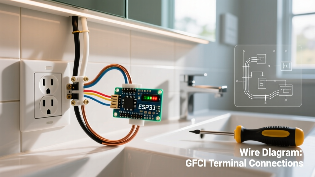

The Critical Role of GFCI Protection in Bathrooms
Water and electricity are a notoriously dangerous combination. Because bathrooms are high-moisture environments with grounded surfaces like metal plumbing and tile floors, the risk of severe electrical shock is exponentially higher than in dry rooms. Installing a properly wired Ground Fault Circuit Interrupter (GFCI) electrical outlet for bathroom vanities is not just a best practice; it is a strict legal requirement under the National Electrical Code (NEC). According to the Electrical Safety Foundation International (ESFI), GFCIs monitor the current flowing through a circuit and trip within 1/40th of a second if they detect a leakage of just 4 to 6 milliamps to ground.
In this comprehensive guide, we will walk you through the professional-grade, step-by-step installation of a 20-Amp Tamper-Resistant GFCI receptacle. We will cover exact NEC box-fill calculations, the crucial difference between LINE and LOAD terminals, and the specific torque requirements to ensure a fire-safe connection.
Understanding NEC Bathroom Circuit Requirements
Before touching a single wire, you must verify that your circuit meets current code standards. The National Fire Protection Association (NFPA) NEC guidelines dictate strict parameters for bathroom receptacles to prevent overloads from high-draw appliances like hair dryers and heated styling tools.
| Parameter | NEC Requirement | Professional Insight |
|---|---|---|
| Circuit Amperage | 20 Amps minimum | Never use a 15A breaker for a bathroom receptacle circuit. |
| Wire Gauge | 12 AWG Copper | 12 AWG handles the 20A load safely; 14 AWG is a fire hazard here. |
| Receptacle Type | GFCI & Tamper-Resistant (TR) | TR shutters prevent children from inserting foreign objects into slots. |
| Circuit Dedication | Receptacle-only circuit | The 20A bathroom circuit cannot power lights, fans, or other rooms. |
Tools and Materials Checklist
To execute this installation safely and to professional standards, gather the following specific tools and materials. Prices reflect average retail costs in 2026.
- Receptacle: Leviton 20-Amp 125-Volt SmartlockPro Self-Test GFCI (Model GFNT2-W) - $24.00
- Voltage Tester: Fluke 1AC-II VoltAlert Non-Contact Voltage Tester - $35.00
- Wire Strippers: Klein Tools 11055 Wire Stripper/Cutter (handles 10-18 AWG) - $28.00
- Torque Screwdriver: Klein Tools 70005 Torque Screwdriver (crucial for terminal specs) - $110.00
- Connectors: Ideal Industries 341 Wire-Nuts (Red) or Wago 221 Lever Nuts - $6.00
- Electrical Box: Carlon B618R-UP 22.5 Cubic Inch Deep Old-Work Box (if replacing a shallow box) - $8.00
Phase 1: Power Verification and Box Assessment
Step 1: Kill the Power and Verify
Locate your main electrical panel and switch off the 20-Amp breaker supplying the bathroom. Do not rely solely on the wall switch. Insert your Fluke 1AC-II tester into the top and bottom slots of the existing outlet. The tip must remain completely dark. For absolute certainty, remove the faceplate and touch the tester directly to the brass and silver terminal screws. As the Consumer Product Safety Commission (CPSC) emphasizes, verifying the absence of voltage is the single most critical safety step in any DIY electrical work.
Step 2: Evaluate Box Fill Capacity
GFCI devices have massive internal electronics, making their bodies significantly deeper than standard duplex receptacles. According to NEC Article 314.16, a standard 12 AWG wire requires 2.25 cubic inches of box volume. A GFCI device counts as two conductors (4.5 cubic inches). When you add grounding wires, cable clamps, and the physical bulk of the Leviton GFNT2-W, you need a minimum 22.5 cubic inch deep electrical box. If your existing box is a standard 14-cubic-inch shallow box, you must upgrade it to a deep box to avoid pinched wires and inevitable short circuits.
Phase 2: Prepping the Wires
Step 3: Strip to the Exact Gauge
Use the 12 AWG hole on your Klein 11055 wire strippers. Strip exactly 3/4 inch of insulation from the black (hot), white (neutral), and bare copper (ground) wires. The Leviton GFNT2-W features a physical 'strip gauge' molded into the back of the device. If you strip too much copper, you risk exposed live metal arcing against the metal box or ground wires. If you strip too little, the insulation will bind under the terminal screw, resulting in a high-resistance connection that will melt under a 1500-watt hair dryer load.
Step 4: Form the J-Hook (For Side-Wiring)
While the Leviton GFCI allows for straight 'back-wiring' (where the screw clamps the wire straight down), many master electricians prefer traditional side-wiring using the terminal screws. Use your needle-nose pliers to form a tight 'J-hook' at the end of the stripped copper. The hook must curve clockwise. This ensures that when you tighten the terminal screw, the screw head pulls the wire loop tighter rather than pushing it out.
Phase 3: The LINE vs. LOAD Distinction
Critical Warning: Miswiring LINE and LOAD is the #1 cause of GFCI failure in DIY installations. LINE brings power from the breaker panel. LOAD sends protected power to downstream outlets. If you wire incoming power to LOAD, the GFCI will either refuse to reset or, worse, it will reset but provide zero ground-fault protection.
Step 5: Identify and Connect LINE
The incoming power cable from the breaker panel connects to the terminals marked LINE (usually covered by a yellow warning tape on new Leviton devices).
- Connect the bare copper ground wire to the green grounding screw. Tighten to 14 in-lbs.
- Connect the white neutral wire to the silver LINE terminal.
- Connect the black hot wire to the brass LINE terminal.
Step 6: Cap the LOAD Terminals (If Not Feeding Downstream)
If this is the only outlet on the bathroom circuit (which is common in modern dedicated 20A layouts), you do not need to use the LOAD terminals. Leave the warning tape over the LOAD terminals. If you are feeding a second GFCI or a standard outlet downstream (e.g., on the other side of a large double vanity), connect the downstream black and white wires to the brass and silver LOAD terminals, respectively.
Phase 4: Securing, Torquing, and Testing
Step 7: Apply Correct Torque
Hand-tightening terminal screws is no longer considered best practice. Loose connections cause arcing, which is a leading cause of residential electrical fires. Set your torque screwdriver to 14 inch-pounds (verify the exact spec printed on the Leviton device packaging, as it can range from 14 to 16 in-lbs). Tighten the LINE and LOAD terminal screws until the torque driver clicks. This ensures optimal metal-to-metal contact without crushing the copper strands.
Step 8: Fold and Mount
Carefully fold the wires into the back of the electrical box using an accordion style. Push the GFCI device into the box, ensuring no bare ground wires are touching the brass or silver terminals. Secure the device using the provided 6-32 mounting screws. Attach the weather-resistant or standard decorative faceplate.
Step 9: The Trip Test
Turn the 20A breaker back on at the panel. The green LED on the Leviton GFNT2-W should illuminate, indicating power is present and the device is set. Press the black TEST button. You should hear a sharp click, the green light should turn off, and the red RESET button should pop out slightly. Plug in a lamp or phone charger to verify the outlet is dead. Finally, press the red RESET button until it clicks into place. The green light will return, confirming your electrical outlet for bathroom installation is fully operational and protecting your home.
Troubleshooting Common Installation Failures
Even with careful attention to detail, issues can arise. Here is how to diagnose the most common GFCI edge cases:
- The GFCI Will Not Reset: This almost always means the LINE and LOAD wires are reversed, or there is no power reaching the LINE terminals. Turn off the breaker, pull the device out, and verify your incoming voltage with a multimeter.
- Nuisance Tripping Under Load: If the outlet trips only when you turn on a high-wattage hair dryer, check for a shared neutral. If another circuit's neutral wire is accidentally bundled with the bathroom neutral in the panel, the GFCI will detect an imbalance and trip immediately.
- Downstream Outlets Are Dead: If you wired downstream outlets to the LOAD terminals but they have no power, check that the downstream wires are securely clamped and that you haven't accidentally daisy-chained a standard receptacle with a broken internal tab.
By adhering to these precise installation steps, utilizing deep electrical boxes, and respecting torque specifications, you ensure your bathroom vanity is equipped with a safe, code-compliant, and highly reliable power source.