
Understanding the Switch and Outlet Combo Device
When space is at a premium or you need to add a switched receptacle without cutting a new hole for a two-gang box, a combination device is the ultimate solution. Finding a clear, accurate diagram for wiring a light switch and outlet in a single yoke can be frustrating, as most online guides gloss over the critical 'split-tab' mechanism that dictates how the circuit behaves. In this comprehensive guide, we will break down the exact wiring topologies for the most common combo devices on the market in 2026, such as the Leviton 5243-W (15A) and the Cooper Wiring Devices 470 (15A), ensuring your installation is both functional and fully compliant with the latest National Electrical Code (NEC) standards.
According to the Electrical Safety Foundation International (ESFI), improper receptacle wiring remains a leading cause of residential electrical fires. By understanding the internal brass and silver terminal architecture, you can eliminate the risk of dead shorts and ensure proper grounding.
Anatomy of a Switch/Outlet Combo Receptacle
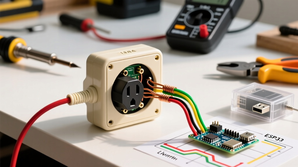
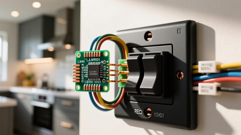
Before interpreting any wiring diagram, you must understand the physical layout of the device. A standard duplex receptacle has two brass (hot) screws and two silver (neutral) screws, connected by a continuous metal fin on each side. A combo device replaces one half of the duplex with a single-pole toggle switch.
The Critical 'Break-Off' Fin
On the hot (brass) side of the receptacle half, you will notice a small metal tab connecting the top and bottom brass screws. This is the break-off fin. In a standard duplex outlet, you snap this fin off to split the receptacle (e.g., making the top half switched and the bottom half always hot). On a combo device, this fin determines whether the switch controls the local outlet, or if the switch and outlet operate entirely independently on separate hot feeds. Leaving this fin intact when it should be removed is the number one cause of tripped breakers during combo installations.
Scenario A: The Switch Controls the Local Outlet
This is the most common diagram for wiring a light switch and outlet combo. It is frequently used in kitchens for garbage disposals, in workshops for power tools, or in bathrooms for ventilation fans plugged into the receptacle.
- Power Source: A single 2-wire cable (14/2 or 12/2 Romex) enters the box, providing line (hot), neutral, and ground.
- Fin Status: The brass break-off fin remains INTACT.
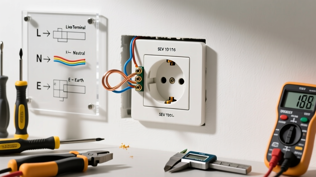
- Wiring Logic: The incoming black (hot) wire is pigtailed to both the switch's brass terminal and the receptacle's brass terminal. The switch's black (load) terminal is wired to the receptacle's second brass terminal. The white (neutral) wire connects directly to the silver terminal, and the bare/green ground connects to the green grounding screw.
- Result: The toggle switch acts as a local disconnect for the receptacle. When the switch is off, the outlet is dead.
Scenario B: The Switch Controls a Downstream Light (Independent)
In this scenario, the outlet needs to be 'always hot' (e.g., for a vacuum cleaner or phone charger), while the switch controls a separate overhead vanity light or ceiling fixture. This requires a different wiring topology and a specific modification to the device.
- Power Source: You need a constant hot feed for the outlet, and a separate 'switch leg' cable running to the overhead light.
- Fin Status: The brass break-off fin must be REMOVED using needle-nose pliers. This isolates the receptacle's hot terminal from the switch's output.
- Wiring Logic: The incoming constant hot (black) wire is pigtailed to the receptacle's brass screw AND the switch's input terminal. The switch's output terminal (often marked with a different color or labeled 'Load') connects to the black wire of the cable running up to the light fixture. The receptacle's silver screw connects to the incoming neutral. The light fixture's neutral is wire-nutted to the main neutral bundle.
- Result: The receptacle has continuous power, while the toggle switch exclusively controls the remote lighting load.
Step-by-Step Installation & Torque Specifications
Modern electrical codes are unforgiving when it comes to loose connections. The NFPA 70 National Electrical Code (specifically Article 110.14(D)) mandates that terminals marked with a tightening torque must be tightened to the manufacturer's specified value using a calibrated torque tool. Guessing the tightness by hand leads to arcing and thermal degradation over time.
Required Tools for a 2026-Compliant Install
- Voltage Tester: Fluke 117 True-RMS Multimeter or a reliable non-contact voltage detector (NCVT) to verify the circuit is de-energized at the breaker panel.
- Wire Strippers: Klein Tools 11055 (for 10-20 AWG) to ensure clean, 3/4-inch wire ends without nicking the copper conductor.
- Torque Screwdriver: CDI Torque screwdriver capable of measuring inch-pounds (in-lbs).
- Connectors: Wago 221 Lever-Nuts for secure, vibration-resistant pigtailing.
Execution Steps
Step 1: Shut off the breaker and verify zero voltage at the bare copper ground and black hot wires.
Step 2: If executing Scenario B, snap off the brass break-off fin. Bend it back and forth until it snaps cleanly; do not use wire cutters, as this can damage the internal rivet.
Step 3: Strip 3/4 inch of insulation from all conductors. Create pigtails using Wago 221 connectors if multiple wires need to share a single terminal.
Step 4: Form a clockwise shepherd's hook on the solid copper wires. Loop them around the terminal screws so that tightening the screw pulls the loop closed, rather than pushing it open.
Step 5: Torque all terminal screws to the manufacturer's specification (see table below).
Step 6: Neatly fold the wires into the back of the box, ensuring the bare ground wire does not touch the brass hot terminals. Secure the device to the box using the provided #6-32 machine screws.
Wire Gauge and Torque Matrix
Matching the correct wire gauge to the circuit breaker and the device rating is non-negotiable. The Consumer Product Safety Commission (CPSC) frequently warns against overloading 15A devices on 20A circuits. While a 20A receptacle can accept 12 AWG wire, a 15A combo device (like the Leviton 5243) should only be installed on a 15A breaker with 14 AWG wire, unless local amendments dictate otherwise.
| Circuit Breaker | Wire Gauge (Copper) | Device Rating | Terminal Torque Spec (Approx) |
|---|---|---|---|
| 15 Amp | 14 AWG | 15A (e.g., Leviton 5243) | 12 to 14 in-lbs |
| 20 Amp | 12 AWG | 20A (e.g., Leviton 5643) | 14 to 16 in-lbs |
| 20 Amp | 12 AWG | 15A (Allowed by NEC 210.21) | 12 to 14 in-lbs |
Note: Always defer to the specific torque value printed on the back of the device yoke or the included instruction sheet, as metallurgy and screw thread pitches vary by manufacturer.
Common Failure Modes and Troubleshooting
Even with a perfect diagram for wiring a light switch and outlet, field conditions can introduce variables that cause the circuit to fail. Here is how to diagnose the three most common post-installation issues:
1. The Breaker Trips Immediately Upon Reset
The Cause: A dead short. This almost always happens in Scenario B when the electrician forgets to break off the brass fin, or accidentally connects the neutral (white) wire to a brass hot terminal. It can also occur if a bare ground wire is pushed too far back and makes contact with the side terminal screws.
The Fix: Remove the device, inspect the fin, and use a multimeter in continuity mode to ensure there is no continuity between the hot and neutral wires with the switch in the 'ON' position.
2. The Switch Works, but the Outlet is Dead
The Cause: The hot feed was wired exclusively to the switch's input terminal, and the pigtail to the receptacle's brass screw was omitted. Alternatively, the break-off fin was removed when it should have been left intact (Scenario A), severing power to the outlet half.
The Fix: Verify the wiring topology. If the outlet needs constant power, ensure the incoming hot is pigtailed to both the switch and the receptacle. If the outlet is meant to be switched, ensure the fin is intact and the switch load terminal feeds the receptacle.
3. The Outlet Works, but the Switch Does Nothing
The Cause: The switch's load terminal (often the black screw) is wired to a neutral bundle, or the downstream light fixture's neutral is disconnected at the ceiling box. Another possibility is that a smart switch was installed in a combo setup without a dedicated neutral wire in the box, causing the internal relay to fail to latch.
The Fix: Trace the switch leg. Ensure the black screw on the switch connects only to the hot wire leading to the light fixture, and verify the light fixture's white wire is properly connected to the main neutral bundle.
Pro-Tip for 2026 Smart Upgrades: If you plan to upgrade the switch half of your combo device to a smart relay (like a Lutron Caseta or Leviton Decora Smart) in the future, you MUST run a 3-wire cable (14/3 or 12/3) to the switch box during the rough-in phase. NEC Article 404.2(C) requires a grounded neutral conductor at the switch location to accommodate modern electronic lighting controls. Standard combo devices do not require a neutral at the switch yoke, but planning ahead saves thousands in drywall repair costs later.
Final Safety Verification
Once the device is secured and the faceplate is installed, restore power at the breaker panel. Use a receptacle tester (like the Gardner Bender GFI-3501) to verify correct wiring at the outlet half. The tester should show two amber lights, indicating 'Correct Wiring'. If it shows 'Hot/Neutral Reverse' or 'Open Ground', immediately cut power and re-evaluate your terminal connections. Mastering the diagram for wiring a light switch and outlet is about more than just making the device work; it is about ensuring a resilient, code-compliant connection that will safely serve your home for decades.