
The Definitive Wiring Diagram Reference
When you need to wire an electrical outlet, guessing the terminal layout or relying on memory is a recipe for arcing faults, tripped breakers, or electrical fires. According to the National Fire Protection Association (NFPA), electrical distribution and lighting equipment are consistently among the leading causes of home structure fires. This reference guide strips away the fluff and provides exact wiring diagrams, terminal mappings, and National Electrical Code (NEC) specifications for standard 15-amp and 20-amp duplex receptacles.
Anatomy of a Standard Duplex Receptacle
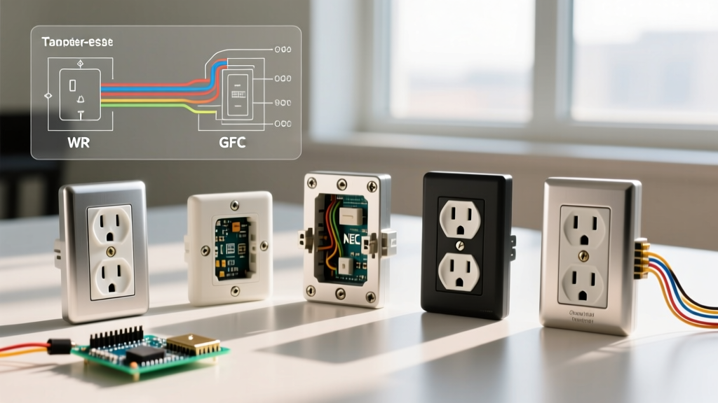
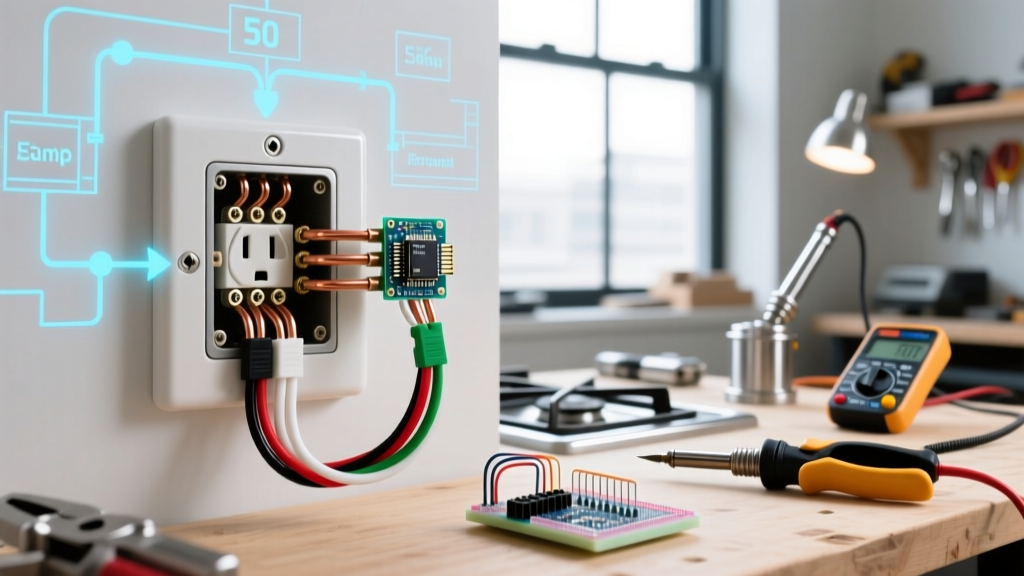
Before interpreting any wiring diagram, you must understand the physical interface of the device. A standard NEMA 5-15R (15A) or 5-20R (20A) receptacle features three distinct terminal zones:
- Brass Terminals (Hot): Accepts the black (or red) ungrounded conductor. The longer slot on the receptacle face corresponds to these screws.
- Silver Terminals (Neutral): Accepts the white or gray grounded conductor. Corresponds to the shorter slot.
- Green Terminal (Ground): Accepts the bare copper or green insulated equipment grounding conductor. Corresponds to the U-shaped pin.
Expert Insight: Never use the "backstab" push-in connectors found on the rear of budget receptacles. While UL-listed, they rely on a small spring-metal wedge that can loosen under thermal cycling. Always use the side-wiring screw terminals or the back-wiring clamp plates (found on commercial-grade models like the Leviton ProGrade 5362, priced around $4.50 per unit).
Core Wiring Diagram Scenarios Matrix
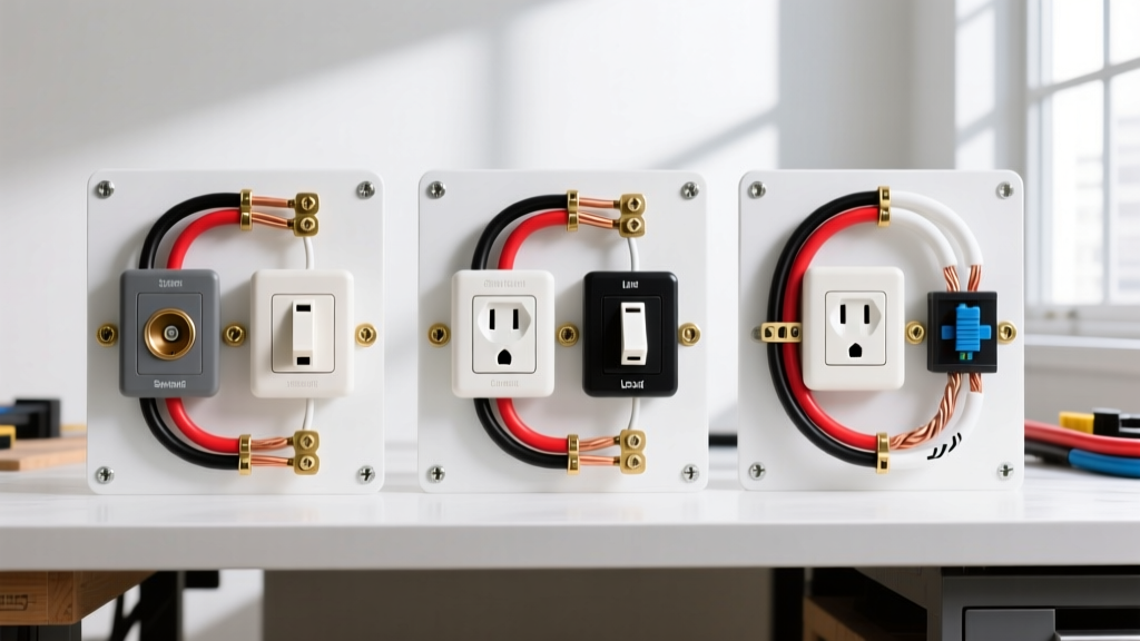
The topology of your circuit dictates the wiring diagram you must follow. Below is a reference matrix for the three most common residential scenarios.
| Scenario | Cable Entering Box | Wires Present | Key Diagram Feature |
|---|---|---|---|
| End-of-Run | 1x 14/2 or 12/2 NM-B | 1 Black, 1 White, 1 Bare | Pigtails not strictly required; direct termination to receptacle. |
| Middle-of-Run | 2x 14/2 or 12/2 NM-B | 2 Black, 2 White, 2 Bare | Requires wire nuts and pigtails to maintain downstream continuity. |
| Split-Receptacle (Half-Hot) | 1x 14/3 or 12/3 NM-B | 1 Black, 1 Red, 1 White, 1 Bare | Break-off brass fin removed; two separate hot sources on one yoke. |
| GFCI Downstream Protection | 2x 14/2 or 12/2 NM-B | 2 Black, 2 White, 2 Bare | Line vs. Load terminal identification is critical. |
Step-by-Step: Wiring an Electrical Outlet (End-of-Run)
This is the foundational diagram where a single cable feeds the final receptacle on a branch circuit.
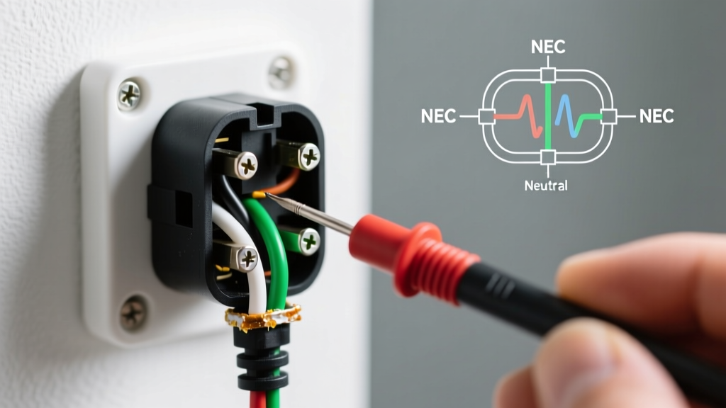
- Verify De-energization: Use a non-contact voltage tester (e.g., Klein Tools NCVT-2, ~$25) and confirm with a digital multimeter probing hot-to-ground (should read 0.00V).
- Strip the Jacket: Remove exactly 5/8-inch of insulation from the individual conductors. Stripping too much leaves exposed copper outside the terminal; stripping too little traps insulation under the screw plate, causing high resistance and heat.
- Form the Shepherd's Hook: Bend the bare copper into a clockwise hook. The clockwise direction ensures that tightening the screw pulls the wire loop tighter, rather than pushing it out.
- Terminate and Torque: Loop the black wire to the top brass screw, white to the top silver screw, and bare to the green ground screw. Crucial: The NEC now mandates the use of a calibrated torque screwdriver. For a standard Leviton 15A receptacle, torque the screws to exactly 14 in-lbs. (A dedicated torque screwdriver like the Klein Tools 60174 costs roughly $130 but prevents terminal strip-out and loose connections).
Advanced Diagram: The Split-Wired (Half-Hot) Receptacle
Common in living rooms and bedrooms, this diagram allows one half of the outlet to be controlled by a wall switch while the other remains constantly hot.
Diagram Execution Steps:
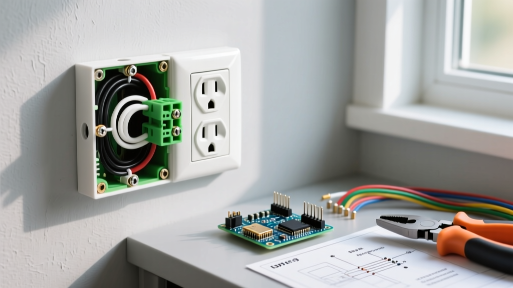
- The Break-Off Fin: Locate the small metal tab connecting the two brass screws on the hot side. Use needle-nose pliers to snap this fin off. Do not break the silver (neutral) fin.
- Wire Mapping: Connect the constant hot (black wire) to one brass screw. Connect the switched hot (red wire from a 3-conductor cable) to the other brass screw.
- Neutral & Ground: The white neutral wire terminates on either silver screw (they are internally bonded). The bare ground goes to the green screw.
- Code Warning (MWBC): If the black and red wires originate from a Multi-Wire Branch Circuit (two separate breakers sharing a neutral), the Occupational Safety and Health Administration (OSHA) and NEC 240.15(B)(1) strictly require a 2-pole breaker or an approved handle tie to simultaneously disconnect both ungrounded conductors, preventing a lethal 240V shock hazard across the broken fin.
NEC 2026 Code Requirements & Box Fill
When executing these diagrams, physical space and modern safety codes are non-negotiable.
- Tamper-Resistant (TR): NEC 406.12 mandates TR receptacles in all dwelling unit areas. The internal shutters prevent children from inserting single objects.
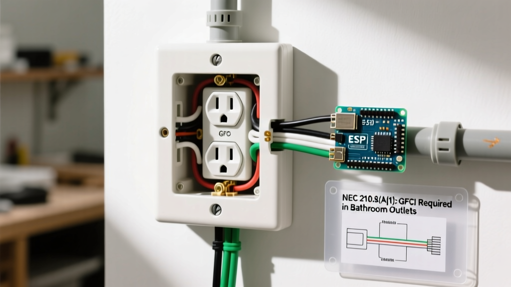
- GFCI & AFCI: Kitchens, bathrooms, garages, and outdoor locations require GFCI protection (NEC 210.8). Living areas and bedrooms require AFCI protection (NEC 210.12), typically handled at the breaker panel.
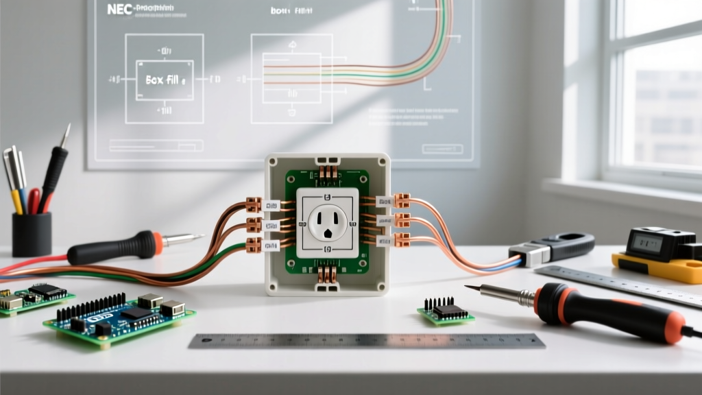
- Box Fill Calculations: Per NEC Article 314.16, a standard single-gang plastic nail-on box (typically 20 to 22 cubic inches) can comfortably house one receptacle, two 14/2 cables, and internal clamps. If you are adding a third cable or using larger 12 AWG wire, you must upgrade to a "deep" 24 cu. in. box to prevent wire crushing, which damages insulation and alters the diagram's intended geometry.
Troubleshooting Common Wiring Faults
Even with a perfect diagram, execution errors occur. Use a 3-prong receptacle tester (e.g., Gardner Bender GRT-300, ~$8) to diagnose:
| Tester Indication | Probable Fault | Danger Level & Fix |
|---|---|---|
| Open Neutral | White wire disconnected or broken upstream. | High (Shock hazard). Check silver terminal torque and upstream wire nuts. |
| Reversed Polarity | Black and white wires swapped on terminals. | High (Appliance shell energized). Move black to brass, white to silver. |
| Bootleg Ground | Jumper wire illegally connecting neutral to ground screw. | Lethal. Remove jumper; run a dedicated equipment grounding conductor. |
Frequently Asked Questions
Can I wire two outlets on the same diagram using the push-in holes?
While the NEC does not explicitly ban push-in (backstab) connections for 14 AWG solid wire, master electricians universally avoid them for middle-of-run diagrams. The internal spring contacts degrade over time, leading to high-resistance faults. Use the screw terminals or back-wire clamps.
Does it matter which brass or silver screw I use for a single end-of-run outlet?
For a standard end-of-run diagram with no downstream loads, it does not matter which brass screw receives the hot wire, as they are bonded by the brass fin. However, establishing a personal standard (e.g., hot to top brass, neutral to top silver) builds muscle memory for more complex split-wired diagrams.
For further reading on residential electrical safety and grounding prerequisites, consult the U.S. Consumer Product Safety Commission (CPSC) Electrical Safety Guide.