
Why Electric Outlet Height From Floor Matters
When wiring a new room or remodeling an existing space, the electric outlet height from floor is a detail that impacts ergonomics, accessibility, and furniture placement. While the National Electrical Code (NEC) is famously strict about outlet spacing (the 6-foot rule under NEC 210.52), it remains surprisingly silent on standard wall outlet heights for residential dwellings. Instead, standard heights are dictated by regional builder conventions, ergonomic best practices, and the Americans with Disabilities Act (ADA) for accessible spaces.
Installing outlets at the wrong height can lead to baseboard interference, blocked furniture, or non-compliance in accessible home designs. This guide provides a meticulous, step-by-step installation framework to ensure your receptacles are perfectly placed, securely wired, and fully compliant with modern safety standards.
Code Requirements vs. Builder Standards
Before cutting into drywall, you must understand the baseline measurements. The standard convention in North America is to place the center of the electrical box 12 to 16 inches above the finished floor. However, if you are building an ADA-compliant space, the rules shift to focus on the bottom of the box.
| Room / Application | Standard Height (Center of Box) | ADA Minimum (Bottom of Box) | Code & Practical Notes |
|---|---|---|---|
| Living Room / Bedroom | 12" - 16" | 15" | Standard builder grade is 12". ADA requires 15" min to bottom of box. |
| Kitchen Countertops | 44" (15"-20" above counter) | N/A (Task specific) | Must be GFCI protected. Never install face-up on horizontal surfaces. |
| Bathroom Vanities | 44" (15" above vanity) | N/A | GFCI required within 3 feet of the outside edge of the basin. |
| Garage / Workshop | 48" | 15" | Elevated to prevent damage from vehicles and heavy floor equipment. |
| Washing Machine | 42" - 48" | N/A | Placed above the water supply valves for emergency disconnect access. |
For comprehensive guidelines on accessible reach ranges, refer to the 2010 ADA Standards for Accessible Design. For general residential electrical spacing and safety rules, consult the National Fire Protection Association (NFPA) NEC guidelines.
Essential Tools for Precision Installation
Achieving the exact electric outlet height from floor requires more than a standard tape measure. Tape measures often hook onto baseboards or uneven subfloors, introducing a 1/2-inch margin of error that can cause outlets to misalign across a room.
- Measuring: Bosch GLM20 Laser Measure (eliminates baseboard hook errors).
- Cutting: Milwaukee M12 Oscillating Multi-Tool with a drywall blade (cleaner cuts than a jab saw).
- Boxes: Klein Tools 53796 Deep 1-Gang Old-Work Boxes (for remodels) or Carlon B618R (for new construction).
- Wiring: Klein Tools 11055 Wire Strippers and a 15A Tamper-Resistant Duplex Receptacle (e.g., Leviton T52-R).
- Fastening: Torque screwdriver calibrated to 14 in-lbs to prevent terminal screw stripping.
Step-by-Step Installation: Hitting the Perfect Height
Phase 1: Measuring and Marking the Rough-In
The most common mistake DIYers make is measuring from the subfloor without accounting for the finished flooring. If you are roughing-in before flooring is laid, you must add the flooring thickness to your target height.
- Determine Finished Floor Elevation: Standard engineered hardwood adds 3/4". Carpet with a standard pad adds roughly 5/8" to 3/4". Tile with mortar adds 1/2" to 5/8".
- Calculate the Mark: If your target is 12" to the center of the box on a finished hardwood floor, and you are currently on a bare plywood subfloor, measure 12-3/4" from the subfloor.
- Mark the Wall: Use a laser level to shoot a horizontal line across the entire room at your calculated height. Mark the center of each stud where the line intersects. This guarantees every outlet in the room is perfectly level, regardless of floor joist sag.
Phase 2: Drywall Cutting and Box Placement
For remodel work (old-work boxes), precision cutting is vital to ensure the drywall isn't damaged, which would compromise the box's mounting ears.
- Hold the Klein Tools 53796 old-work box against the wall at your laser line mark.
- Trace the outside of the box with a carpenter's pencil.
- Using your oscillating multi-tool, cut just inside the pencil line. Cutting outside the line will result in a gap that the outlet cover plate may not fully conceal.
- Insert the box into the wall cavity. Tighten the mounting screws clockwise. The internal flippers will rotate and clamp securely against the back of the 1/2" or 5/8" drywall.
Phase 3: Wiring the Receptacle
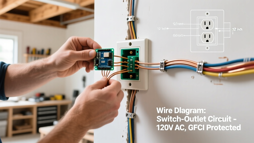
With the box mounted at the correct height, pull your 14/2 NM-B cable (for 15A circuits) or 12/2 NM-B (for 20A circuits) through the knockout.
- Strip the Cable: Remove exactly 3/4" of insulation from the black (hot), white (neutral), and bare copper (ground) wires.
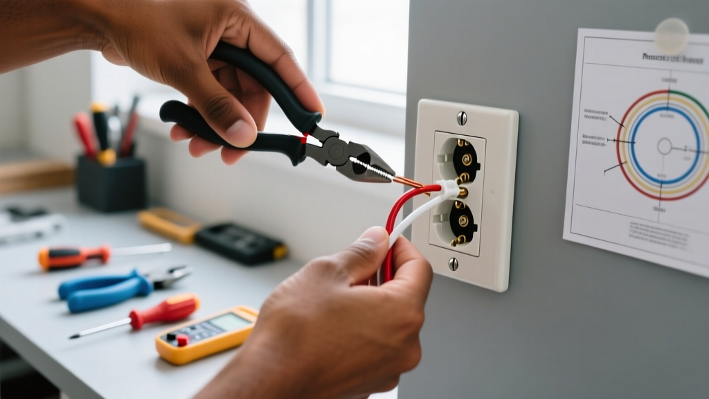
- Form the Loop: Use needle-nose pliers to create a tight, clockwise hook at the end of each wire. The clockwise direction ensures the wire wraps into the terminal when the screw is tightened, rather than being pushed out.
- Connect and Torque: Attach the ground to the green screw, neutral to the silver screw, and hot to the brass screw. Use a torque screwdriver set to the manufacturer's specification (typically 7 to 14 in-lbs for Leviton receptacles). Under-torqued connections are a leading cause of arc faults and residential fires, a hazard heavily emphasized by the Electrical Safety Foundation International (ESFI).
Phase 4: Mounting and Final Leveling
Even if your drywall cut was perfect, the wall itself might be slightly bowed, causing the outlet to sit crooked.
- Fold the wires neatly into the back of the box using a "Z-fold" technique (accordion style) to prevent pinching.
- Insert the receptacle and thread the #6-32 machine screws into the mounting ears.
- Before fully tightening, place a 2-inch torpedo level across the top of the receptacle yoke (the metal strap).
- If the outlet is tilted, loosen the screws slightly, tap the yoke with a screwdriver handle to rotate it, and retighten. If the box is recessed too deeply into the wall, add a 1/16" or 1/8" plastic receptacle shim behind the mounting ears to bring it flush with the drywall.
Edge Cases: Baseboards, Concrete, and Thick Carpets
Pro-Tip for Baseboard Interference: If you are installing in a room with tall, ornate baseboards (6 inches or higher), a standard 12" outlet height will place the bottom of the cover plate directly on the baseboard trim. In these scenarios, raise your electric outlet height from floor to 18" or 20" to the center of the box to ensure the standard 4.5" cover plate clears the trim entirely.
Concrete and Masonry Walls: In basements or slab-on-grade construction, running wires inside the wall isn't an option. You must use surface-mounted raceways (like Legrand Wiremold) or frame out a 2x4 stud wall. If framing a stud wall against concrete, ensure a 1/2" foam sill sealer is placed under the bottom plate to prevent moisture wicking, which can rot the wood and alter your floor-to-plate measurements over time.
Thick Plush Carpets: In high-end homes with thick wool carpets and heavy padding, the finished floor can compress by up to an inch when walked on. If you measure 12" from the uncompressed carpet surface, the outlet may end up visually "sinking" into the carpet. Always measure from the hard subfloor and add a fixed 3/4" for standard carpet assemblies, regardless of how thick the carpet feels to the touch.
Frequently Asked Questions
Can I install outlets horizontally near the floor?
No. While the NEC does not explicitly ban horizontal wall receptacles, standard cover plates are designed for vertical mounting. More importantly, installing a receptacle horizontally near the floor increases the risk of a plug pulling partially out, exposing the prongs, and allowing a spilled liquid or conductive dust to short across the live terminals. Always mount standard wall outlets vertically with the ground pin facing down (or up, depending on local inspector preference, but consistently vertical).
Does the NEC require a specific height for garage outlets?
The NEC does not mandate a specific height for garage receptacles, but local building codes often require them to be installed at least 18 inches above the floor. This is primarily to prevent physical damage from vehicles, toolboxes, and wet floors. A 48-inch height is the industry best practice for garages, placing the outlet at workbench level and safely out of the splash zone.
How do I change the height of existing outlets during a remodel?
To raise or lower an existing outlet, you must cut a new hole at the desired height and fish the existing NM-B cable to the new location. If the existing cable is too short, you cannot simply add an extension inside the wall cavity. You must install a junction box at the old location, make your splices using WAGO 221 lever nuts, cover it with a blank faceplate, and run a new continuous cable to the new box height. All splices must remain accessible; they cannot be buried behind drywall.