
Understanding the Wiring Diagram for Light Switch to Multiple Lights
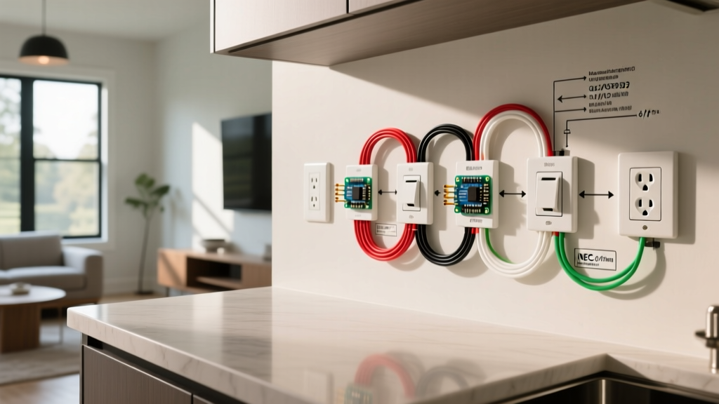
Wiring a single-pole switch to control multiple light fixtures is one of the most common residential electrical tasks. Whether you are illuminating a long hallway, a multi-bulb vanity, or a series of recessed LED downlights in a kitchen, the underlying principle remains the same: a parallel circuit configuration commonly referred to as 'daisy chaining.' In 2026, with the widespread adoption of high-efficiency LED fixtures and smart home integrations, understanding the exact wiring diagram for light switch to multiple lights is more critical than ever. Modern LED drivers can introduce inrush currents, and smart switches often require a neutral wire, making precise termination and load calculation essential for long-term reliability.
This comprehensive guide provides a step-by-step installation framework, adhering strictly to the National Electrical Code (NEC). We will cover cable routing, box fill calculations, precise wire stripping measurements, and termination best practices to ensure your multi-light circuit operates safely and flawlessly.
CRITICAL SAFETY WARNING: Before beginning any electrical work, you must de-energize the circuit at the main service panel. According to OSHA's Control of Hazardous Energy standards, always use a lockout/tagout (LOTO) procedure or secure the breaker with a physical padlock to prevent accidental re-energization while you are working inside the junction boxes.
Why Parallel (Daisy Chain) and Never Series?
In a standard residential 120V AC circuit, lights must be wired in parallel. If you were to wire them in series, the voltage would drop across each fixture (e.g., three lights would each receive only 40V), resulting in dim illumination and premature failure of LED drivers. Furthermore, in a series circuit, if one bulb fails or a connection breaks, the entire circuit opens, and all lights go out. A parallel daisy chain ensures that every fixture receives the full 120V from the load side of the switch, maintaining consistent brightness and independent operational integrity.
Tools and Materials Matrix
Using the correct materials prevents overheating, voltage drop, and mechanical failure. Below is the required bill of materials for a standard 15-ampere lighting circuit.
| Category | Specification / Model | Purpose & NEC Requirement |
|---|---|---|
| Cable | 14/2 NM-B (Romex) with Ground | Standard for 15A lighting circuits (NEC 334). Use 12/2 for 20A circuits. |
| Switch | Leviton Decora 5603-2W (15A) | Single-pole, side-wired. Avoid 'backstab' push-in terminals. |
| Voltage Tester | Fluke 1AC-II VoltAlert | Non-contact verification of de-energized state. |
| Wire Strippers | Klein Tools 11055 | Precise 14 AWG stripping without nicking the copper conductor. |
| Wire Connectors | IDEAL 341 (Orange) or 33 (Yellow) | UL-listed for combining up to four 14 AWG solid conductors. |
| Pigtails | 14 AWG THHN (Stranded or Solid) | Required for grounding and neutral bundling in crowded boxes. |
Step-by-Step Installation Guide
Step 1: Circuit De-energization and Verification
Turn off the breaker controlling the room. Do not rely solely on wall switches being in the 'off' position. Use your Fluke 1AC-II tester on a known live circuit (like an extension cord) to verify the tool works, then test the target circuit at an existing outlet or fixture. Finally, open the first light fixture box and test the exposed wire ends. For authoritative guidelines on residential electrical safety and verification, refer to the U.S. Consumer Product Safety Commission (CPSC) electrical safety library.
Step 2: Routing and Securing the NM-B Cable
Run the 14/2 NM-B cable from the power source (either the panel or an upstream junction box) to the switch box, and then from the switch box to Light Fixture #1, Light Fixture #2, and so on. According to NEC Article 334.30, NM cable must be secured within 8 inches of every electrical box and at intervals not exceeding 4.5 feet. Use 1/2-inch plastic cable staples, driving them snug but not so tight that they deform the cable jacket, which could damage the internal insulation.
Step 3: Wiring the Switch Box (Line and Load)
At the switch box, you will have the 'Line' (incoming power) and the 'Load' (outgoing power to the first light).
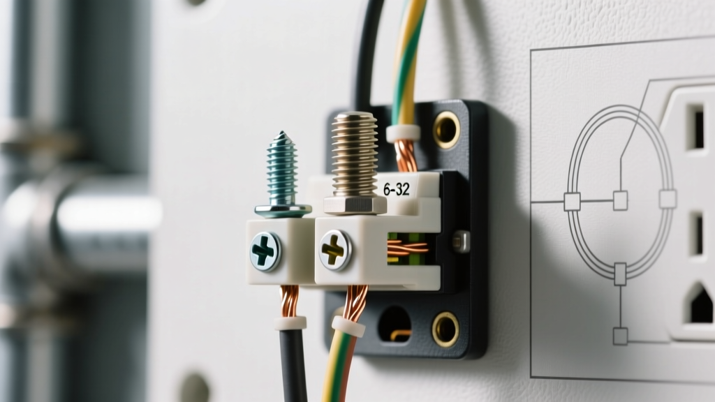
- Grounding: Connect all bare copper ground wires together using an orange IDEAL 341 wire nut. Add a 6-inch 14 AWG bare copper pigtail to this bundle and connect the other end to the green grounding screw on the switch.
- Neutral: Connect all white neutral wires together with a wire nut. Note: Standard single-pole switches do not interrupt the neutral. However, if you are installing a smart switch, timer, or dimmer, you will need to connect the switch's white neutral wire to this bundle.
- Hot (Line): Connect the incoming black (hot) wire to the bottom brass screw on the switch. Strip exactly 3/4 inch of insulation for screw-terminal wrapping, or 5/8 inch if using the side-clamp plate.
- Switched Leg (Load): Connect the outgoing black wire (heading to Light #1) to the top brass screw on the switch.
Step 4: Daisy Chaining the Light Fixtures
At Light Fixture #1, you will have incoming power from the switch and outgoing power to Light Fixture #2.
- Grounds: Bundle all bare grounds with a wire nut and attach a pigtail to the fixture's green ground screw or ground clip.
- Neutrals: Bundle the incoming white, outgoing white, and the fixture's white wire together. If using a wire nut, ensure no bare copper is exposed outside the skirt of the nut.
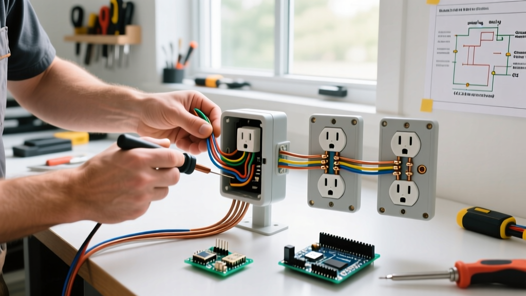
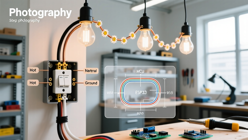
- Hots: Bundle the incoming black (switched hot), the outgoing black (to the next light), and the fixture's black wire together. This is the core of the daisy chain wiring diagram for light switch to multiple lights.
Repeat this exact process at Light Fixture #2, #3, and so on. At the final fixture in the chain, you will only have the incoming cables and the fixture wires—no outgoing cables.
Step 5: Termination Torque and Mechanical Check
While NEC Article 110.14(D) primarily mandates calibrated torque tools for breakers and heavy lugs, best practice for residential switches involves ensuring screw terminals are 'snug.' A loose connection creates high resistance, leading to arcing and heat. Give every wire a gentle 'pull test' (about 1-2 lbs of force) to ensure it is firmly seated under the screw head or inside the wire nut.
NEC Box Fill Calculations (Article 314)
One of the most common code violations in multi-light installations is overcrowding the switch box. The National Fire Protection Association (NFPA) NEC Article 314 dictates strict volume requirements. For 14 AWG wire, each conductor counts as 2.0 cubic inches.
- Hot In (Line): 1 count
- Hot Out (Load): 1 count
- Grounds: 1 count (regardless of how many enter the box)
- Device Yoke (Switch): 2 counts
- Total Count: 5
- Required Volume: 5 x 2.0 = 10.0 cubic inches.
A standard single-gang 'old work' drywall box typically offers 14 to 18 cubic inches, which is sufficient. However, if you are daisy-chaining power *through* the switch box to another room, the conductor count increases, and you must upgrade to a deep single-gang box (22+ cu in) or a double-gang box to remain compliant.
Troubleshooting Common Failure Modes
Even with a correct wiring diagram, installation errors can occur. Use this matrix to diagnose issues before closing up the drywall.
| Symptom | Probable Cause | Diagnostic & Fix |
|---|---|---|
| Breaker trips instantly upon switch toggle. | Short circuit (Hot touching Ground or Neutral). | Inspect all wire nuts at the fixtures. Ensure no bare copper from the black wire is touching the ground bundle or metal box. |
| Lights flicker or buzz (especially LEDs). | Loose neutral or incompatible dimmer. | Check the neutral bundle in the switch box. If using a dimmer, verify it is rated for LED loads (e.g., Lutron Diva DVCL-153P). |
| Switch works, but downstream lights do not. | Open circuit in the daisy chain. | The outgoing hot or neutral at the first fixture is disconnected. Re-terminate the 3-wire bundles at Light #1. |
| Switch feels warm to the touch. | Overloaded circuit or backstabbed terminals. | Calculate total wattage. Move wires from push-in backstabs to the side screw terminals for a secure mechanical bond. |
Final Testing and Commissioning
Once all fixtures are mounted and the switch cover plate is installed, remove the LOTO device and restore power at the panel. Toggle the switch. All lights should illuminate simultaneously without delay or flicker. Use a non-contact voltage tester around the perimeter of the switch plate and fixture canopies to ensure no stray voltage is present on the exterior hardware. By following this exact wiring diagram for light switch to multiple lights, you ensure a safe, code-compliant, and highly reliable lighting circuit that will serve your home for decades.