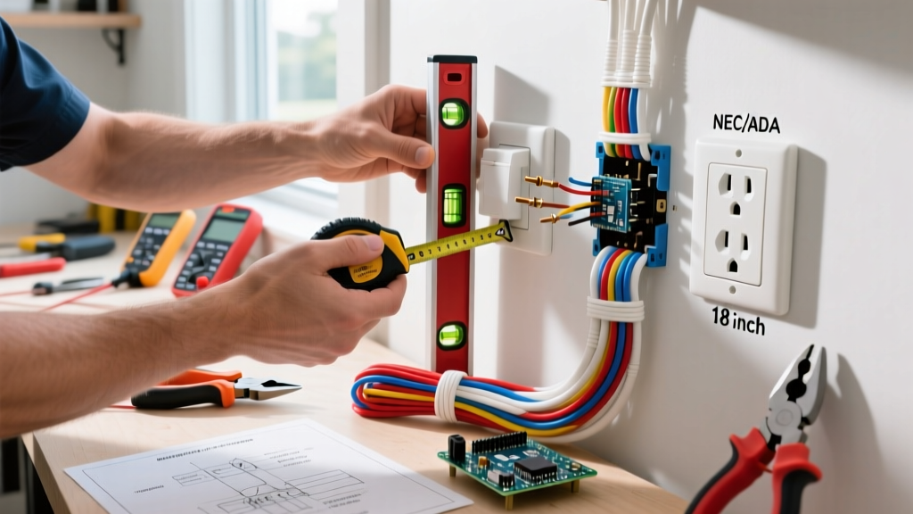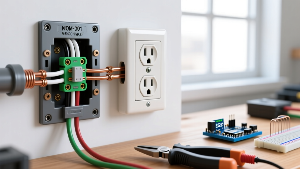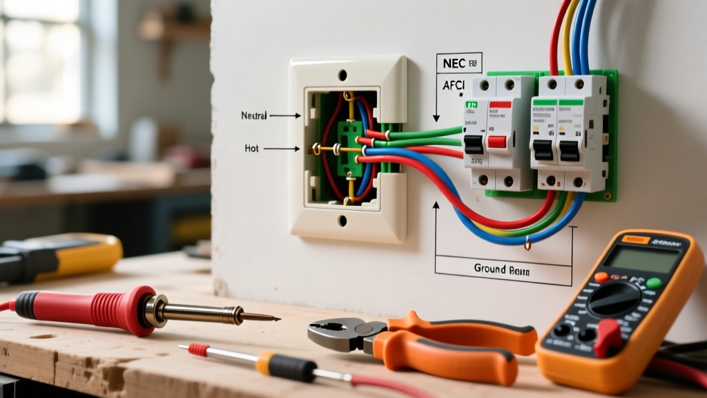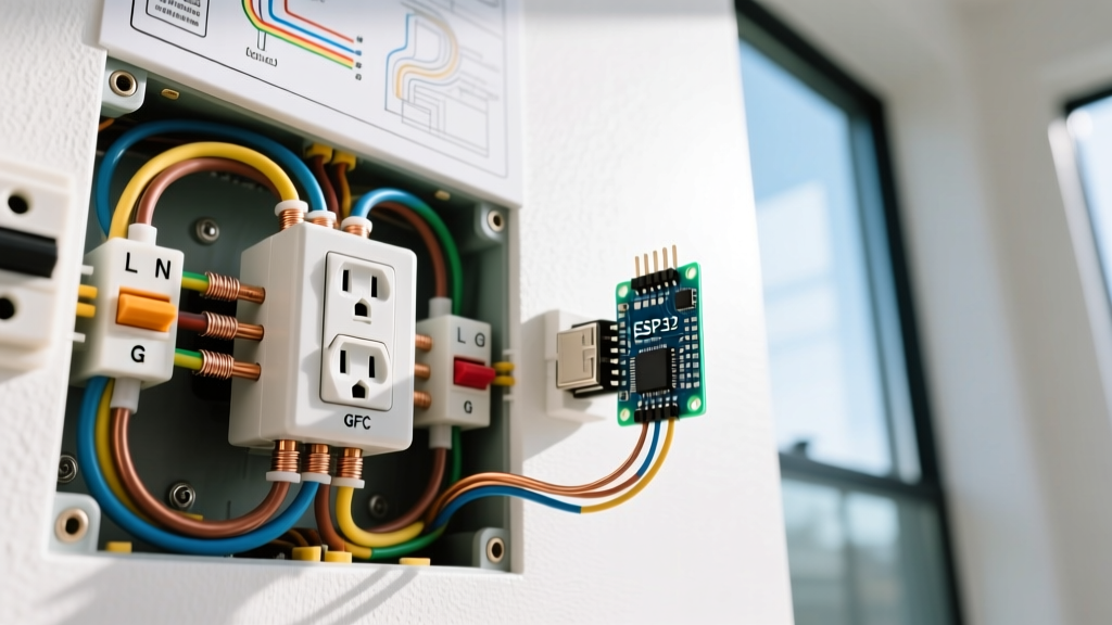

The Hidden Danger of a Reverse Electrical Outlet
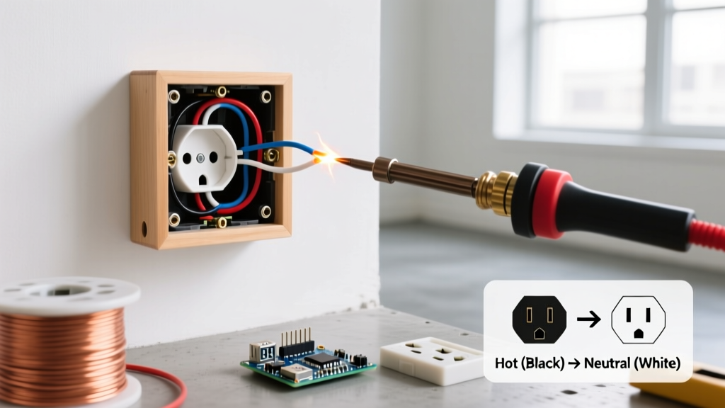
Encountering a reverse electrical outlet during a home inspection or DIY troubleshooting session is one of the most common, yet frequently underestimated, wiring faults in residential electrical systems. Reversed polarity occurs when the hot (ungrounded) and neutral (grounded) conductors are swapped at the receptacle terminals. While the connected appliance may still power on, this fault creates a severe shock hazard because the appliance's internal switch only interrupts the hot wire. If reversed, the appliance's internal components remain energized at 120V even when turned off.
As of 2026, simply swapping the wires back to their correct terminals is no longer considered best practice. Modern electrical codes demand comprehensive safety upgrades when opening a junction box. This guide provides a deep-dive diagnostic and replacement protocol to correct a reverse electrical outlet while upgrading your hardware to meet current National Electrical Code (NEC) standards.
Diagnostic Toolkit: Verifying the Reverse Electrical Outlet
Before touching a screwdriver, you must definitively confirm the fault. Relying on visual wire colors in older homes is a critical error; previous DIYers often misused white wires as hot legs in switch loops. Use a two-tiered testing approach.
1. The Plug-In Receptacle Tester
A standard 3-light tester (such as the Klein Tools RT250) provides an immediate visual fault map. Insert the tester into the suspect receptacle. If the two right-side lights illuminate while the left light remains dark, the device indicates 'Hot/Neutral Reverse'. This confirms a reverse electrical outlet condition.
2. Digital Multimeter Verification
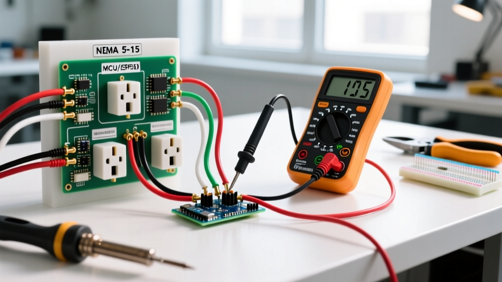
For absolute certainty, especially in circuits with high impedance or phantom voltages, use a True-RMS digital multimeter (e.g., Fluke 117).
- Hot to Neutral: Should read ~120V. If it reads 0V but Hot to Ground reads 120V, polarity is reversed.
- Neutral to Ground: Should read < 2V. If it reads ~120V, the hot and neutral are definitively swapped at the termination point.
Receptacle Fault Matrix: Identifying Wiring Errors
Understanding how different faults present on a tester prevents misdiagnosis. Refer to this matrix when evaluating your circuit:
| Fault Condition | Tester Light Pattern (Left-Center-Right) | Primary Risk Factor |
|---|---|---|
| Correct Wiring | Off - On - On | None (Baseline safe) |
| Reverse Electrical Outlet (Polarity) | On - On - Off | Shock hazard from appliance chassis |
| Open Neutral | On - Off - Off | Device failure, potential overvoltage |
| Open Ground | Off - On - Off | No fault-clearing path for surges |
| Hot/Neutral Reverse + Open Ground | On - Off - Off | Critical shock and fire hazard |
The 2026 Upgrade Matrix: Choosing Your Replacement Receptacle
When fixing a reverse electrical outlet, the NEC requires that any replaced receptacle must comply with current code mandates for that specific location. Do not simply reinstall a legacy standard duplex receptacle. Choose your upgrade path based on the room's requirements.
| Receptacle Type | Model Example | Avg. Cost (2026) | Required Locations (NEC 2023/2026) |
|---|---|---|---|
| 15A Tamper-Resistant (TR) | Leviton T5320-W | $3.50 - $5.00 | All general dwelling unit wall spaces |
| 15A GFCI / TR | Eaton GFTR15-W | $22.00 - $28.00 | Kitchens, bathrooms, garages, outdoors, crawlspaces |
| 15A Dual-Function (AFCI/GFCI) | Leviton AGTR15-W | $38.00 - $45.00 | Laundry rooms, kitchens (where AFCI + GFCI overlap) |
Step-by-Step Replacement & Polarity Correction
Follow this precise procedure to safely eliminate the reverse electrical outlet fault and terminate the new device to modern torque standards.
Step 1: Lockout, Tagout, and Dead-Front Verification
Shut off the branch circuit breaker at the main panel. Apply a physical lockout/tagout device to prevent accidental re-energization—a standard emphasized by the Occupational Safety and Health Administration (OSHA) for all electrical work. Verify the circuit is dead using your non-contact voltage tester (NCVT) and multimeter.
Step 2: Wire Preparation and Stripping
Remove the old receptacle. Inspect the wire insulation. If you are working with older cloth-sheathed NM cable where the white wire was incorrectly used as a hot leg, you must wrap the white wire's insulation with black electrical tape or heat-shrink tubing to permanently re-identify it as an ungrounded (hot) conductor.
Use the wire stripper's built-in gauge to strip exactly 3/4 inch of insulation from the 14 AWG or 12 AWG solid copper conductors. This ensures the wire wraps fully around the terminal screw without exposing bare copper outside the screw head, which could cause a short circuit.
Step 3: Correct Terminal Termination
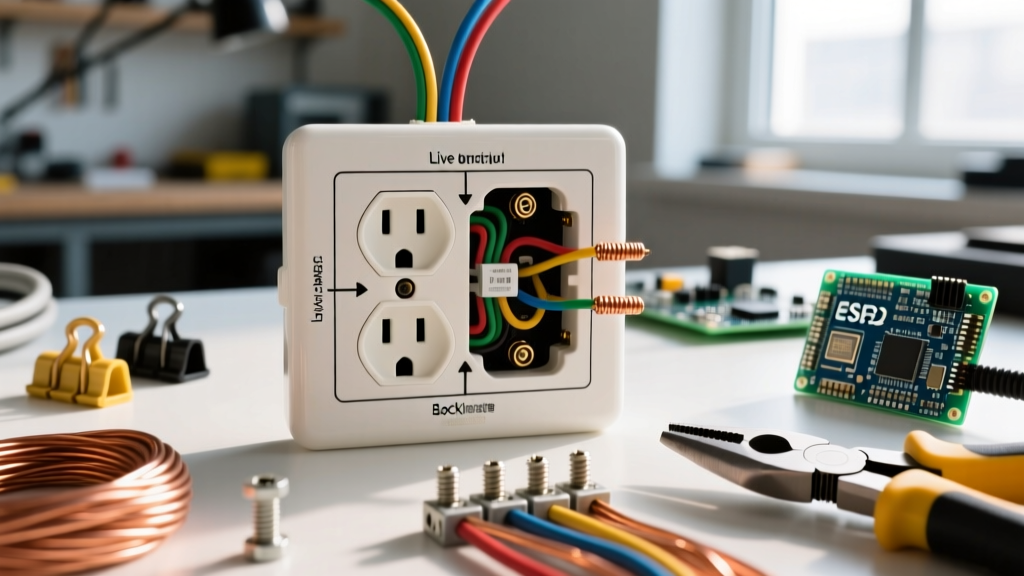
To fix the reverse electrical outlet, the wires must land on their legally mandated terminals:
- Black (or re-identified white) Hot Wire: Must connect to the Brass/Gold terminal screw.
- White Neutral Wire: Must connect to the Silver terminal screw.
- Bare/Green Ground Wire: Must connect to the Green grounding screw.
Form a clockwise J-hook in the wire so that tightening the screw pulls the loop closed rather than pushing it out.
Step 4: Torque to NEC Specifications
Since the 2017 NEC cycle (and heavily enforced through 2026), National Fire Protection Association (NFPA) code 110.14(D) requires terminations to be tightened to the manufacturer's specified torque using a calibrated torque tool. For standard 15A residential receptacles:
- 14 AWG Copper: 14 in-lbs
- 12 AWG Copper: 16 in-lbs
Use an inch-pound torque screwdriver (e.g., Wiha 320P) to secure the connections. This prevents thermal loosening and arc faults over time.
Code Insight: The U.S. Consumer Product Safety Commission (CPSC) notes that loose or improperly torqued terminal connections are a leading cause of residential electrical fires. Correcting polarity is only half the battle; mechanical integrity ensures long-term safety.
Troubleshooting Edge Cases in Older Homes
When correcting a reverse electrical outlet in pre-1970s homes, you may encounter anomalous wiring that defies standard color coding.
The Switch Loop Trap
In older 2-wire switch loops, the white wire in the ceiling-to-switch cable is used as the permanent hot feed to the switch, while the black wire is the switched hot returning to the light. If this cable was mistakenly extended to a receptacle, you will have a reversed polarity scenario where both the black and white wires are technically 'hot' at different times. Solution: You must trace the cable back to the junction box and re-route a proper 3-wire (with ground) NM-B cable to the receptacle box to establish a true dedicated neutral.
Shared Neutrals (Edison Circuits)
If testing reveals that the neutral wire is carrying current even when the local hot wire is disconnected, you are dealing with a multi-wire branch circuit (MWBC). Turning off only one breaker leaves the shared neutral energized by the adjacent phase. Always identify and lock out both adjacent breakers before servicing an MWBC receptacle.
Frequently Asked Questions
Can a reverse electrical outlet damage my electronics?
Yes. While basic resistive loads (like a toaster) will function normally, sensitive electronics with single-pole power switches may retain full line voltage on their internal logic boards when 'turned off'. This accelerates component degradation and increases the risk of internal short circuits.
Does a GFCI receptacle protect against reverse polarity?
No. A GFCI monitors the current differential between the hot and neutral conductors to detect ground faults (current leaking to a person or ground). It does not monitor or correct the physical orientation of the hot and neutral wires. A reverse electrical outlet will still pose a shock hazard on the load side of a GFCI if the appliance's internal chassis becomes energized.
Why did my new receptacle tester show 'Correct' but my multimeter showed reversed polarity?
Cheap plug-in testers rely on specific impedance paths to illuminate their neon lamps. In circuits with high-resistance neutral connections or bootleg grounds (where the neutral and ground are illegally jumpered at the receptacle), a 3-light tester can be fooled into displaying a 'Correct' pattern. Always trust a True-RMS digital multimeter over a simple light tester.