
Diagnosing the Root Cause of an Electric Outlet Shock
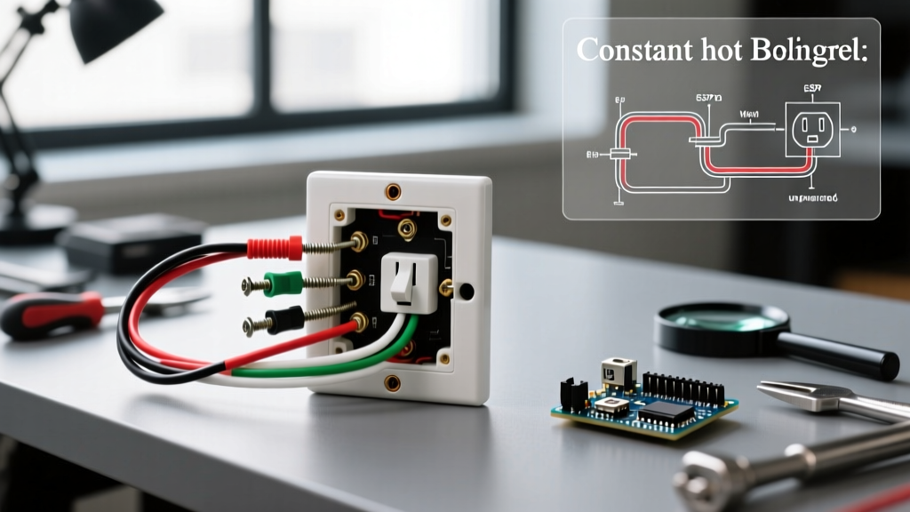
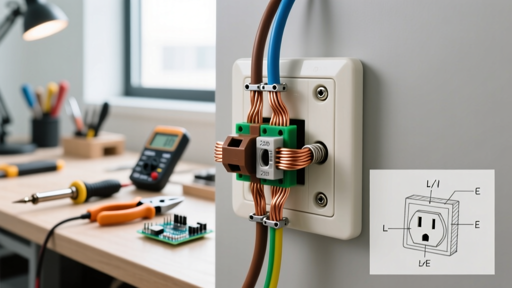
Feeling a jolt from a wall receptacle is not just a nuisance; it is a critical safety hazard that demands immediate attention. According to the U.S. Consumer Product Safety Commission (CPSC), electrical receptacles and wiring are involved in thousands of severe injuries and fatal electrocutions annually. Before grabbing a screwdriver to replace a component, you must understand the exact physics of why the shock is occurring. An electric outlet shock typically stems from one of four specific failure modes in residential wiring.
The 4 Primary Causes of Receptacle Shocks
- Open Ground (Missing Equipment Ground): A 3-prong outlet is installed, but the bare copper ground wire is disconnected or missing entirely. If a plugged-in appliance develops an internal short to its metal chassis, the chassis becomes energized at 120V, waiting for a human to complete the circuit to earth.
- Reverse Polarity: The hot (black) and neutral (white) wires are swapped at the terminal screws. The appliance might still function, but the internal switch only breaks the neutral path, leaving the device's internal components energized even when turned off.
- Capacitive Coupling (The 'Laptop Tingle'): A harmless but alarming micro-shock felt when touching aluminum laptops or metal appliances. This is caused by Y-capacitors in switch-mode power supplies leaking less than 0.25mA to the chassis when a true ground is absent.
- Degraded Insulation or Arcing: Old, brittle insulation or 'backstabbed' push-in wire connections can cause stray voltage to leak onto the metal mounting strap or faceplate screws.
Diagnostic Matrix: Symptom vs. Solution
| Observed Symptom | Probable Cause | Required Action |
|---|---|---|
| Sharp, painful shock from appliance chassis | Open Ground + Appliance Fault | Install GFCI receptacle or run new ground wire |
| Tester shows 'Hot/Neu Reverse' | Swapped terminal wires | Swap black and white wires on LINE terminals |
| Faint vibrating tingle from laptop | Y-Capacitor leakage (No Ground) | Provide true equipment ground (GFCI won't fix this) |
| Shock from touching faceplate screw | Stray voltage / Arcing | Replace receptacle, use screw terminals, check box ground |
Step-by-Step GFCI Installation to Eliminate Shock Hazards
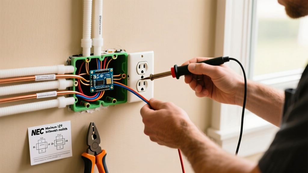
When a true equipment ground wire is unavailable (common in pre-1960s homes), the National Electrical Code (NEC) Article 406.4(D)(2)(b) permits the installation of a Ground Fault Circuit Interrupter (GFCI) to replace a standard 2-prong or faulty 3-prong receptacle. A GFCI does not create a ground; instead, it monitors the current differential between the hot and neutral wires. If it detects a leakage as small as 4 to 6 milliamps—meaning current is escaping through a human—it trips in under 25 milliseconds, preventing a lethal electric outlet shock.
2026 Code Compliance Note: The latest NEC updates strictly emphasize torque specifications for terminal screws to prevent thermal expansion and arcing. You must use a calibrated torque screwdriver for all new receptacle installations.
Materials and Tools Required (2026 Pricing)
| Item | Specific Model | Est. Cost |
|---|---|---|
| 20-Amp GFCI Receptacle | Leviton SmartlockPro R52-08599-00W | $18.50 |
| GFCI / Wiring Tester | Klein Tools RT250 | $29.00 |
| True-RMS Multimeter | Fluke 117 | $195.00 |
| Torque Screwdriver | Klein 32500TORQ (or Wiha 604) | $45.00 |
| Wire Strippers | Klein 11057 (8-20 AWG) | $32.00 |
Step 1: Isolate the Circuit and Verify Zero Energy
Never rely solely on a breaker label. Turn off the breaker and use your Fluke 117 multimeter to test the existing outlet. Insert the probes into the hot (short slot) and neutral (long slot). The reading must be exactly 0.00V. Next, test hot to ground, and neutral to ground. As the Occupational Safety and Health Administration (OSHA) mandates in their electrical safety guidelines, verifying the absence of voltage with a rated, functioning meter is a non-negotiable step before touching any bare conductors.
Step 2: Extract the Old Receptacle and Inspect
Unscrew the faceplate and remove the mounting strap. Pull the receptacle out of the junction box. Inspect the wiring. If the wires are pushed into the back of the device (backstabbed), use a small flathead screwdriver to release the tension and pull them out. Backstabbed connections are notorious for loosening over time, causing arcing and stray voltage that can lead to shocks. You will be terminating the new GFCI using the side-binding screw terminals only.
Step 3: Identify LINE vs. LOAD
Look at the back of the Leviton GFCI. You will see two sets of terminals marked LINE and LOAD, separated by a yellow warning tape.
LINE brings power from the breaker panel.
LOAD sends protected power downstream to other outlets.
If you are only protecting this single outlet, you will only use the LINE terminals. If you are unsure which wires are the LINE, keep the wires separated, turn the breaker back on temporarily, and carefully use your multimeter to identify which pair reads 120V. Turn the breaker back off before proceeding.
Step 4: Strip, Terminate, and Torque
- Use your wire strippers to strip exactly 3/4-inch of insulation from the black (hot) and white (neutral) wires.
- Hook the black wire clockwise around the brass LINE terminal screw. This ensures the screw pulls the wire tighter as it is tightened.
- Hook the white wire clockwise around the silver LINE terminal screw.
- Set your torque screwdriver to 14 in-lbs (check the manufacturer spec sheet included with the Leviton device). Tighten both screws until the torque driver clicks. This prevents the thermal cycling that causes loose connections and fire hazards.
Step 5: Manage the Ground Wire and Apply Labels
If your junction box is metal and properly grounded, connect the bare copper ground wire to the green grounding screw on the GFCI. However, if you are upgrading an old 2-prong circuit with no ground wire present, leave the green screw empty. You must apply the included yellow label that reads 'No Equipment Ground' to the faceplate. This is a strict NEC requirement to inform future users that while they are protected from lethal shocks by the GFCI, surge protectors plugged into this outlet will not function correctly, as they require a true ground path to divert transient voltage spikes.
Step 6: Secure, Restore Power, and Test
Carefully fold the wires into the box, ensuring no bare copper is exposed outside the terminal block. Mount the GFCI and attach the faceplate. Restore power at the breaker. The green LED on the Leviton SmartlockPro should illuminate. Plug in the Klein Tools RT250 tester and press the black test button. The outlet should instantly trip, cutting power and popping the reset button. If it trips, your installation is successful, and the electric outlet shock hazard has been effectively mitigated.
Edge Cases: When to Call a Licensed Electrician
While a GFCI upgrade solves the vast majority of shock hazards in older homes, certain scenarios require professional intervention and a complete circuit rewiring:
- Aluminum Wiring: If your wires are silver-colored (common in the late 1960s and 1970s), you cannot use standard copper-rated GFCIs. You must use CO/ALR rated devices or have an electrician pigtail the aluminum to copper using AlumiConn connectors to prevent galvanic corrosion and subsequent arcing.
- Melted Insulation or Burn Marks: If you pull the old receptacle out and see black soot or melted wire insulation, the circuit has experienced severe overheating. The damaged wire must be cut back or replaced entirely.
- Knob-and-Tube Wiring: If you discover ceramic knobs and cloth-covered wires without a ground, upgrading to a GFCI is permitted for safety, but the National Fire Protection Association (NFPA) strongly recommends planning a full panel and branch circuit upgrade due to the degradation of century-old cloth insulation.
Frequently Asked Questions
Will a GFCI stop my laptop from giving me a mild tingle?
No. A GFCI protects against lethal ground faults (current escaping to earth). The 'laptop tingle' is caused by EMI-filtering Y-capacitors inside your power brick intentionally bleeding a fraction of a milliamp to the chassis. Without a physical ground wire to carry this away, it passes through your skin. To fix the tingle, you must install a true equipment ground wire back to the panel.
Can I install a GFCI on a 15-Amp breaker if the outlet is rated for 20-Amps?
Yes. The NEC allows a 20-Amp rated receptacle (which has both a standard 15-Amp vertical slot and a horizontal T-slot) to be installed on a 15-Amp circuit, provided it is a single receptacle on that yoke or part of a standard residential branch circuit. Using a 20-Amp GFCI like the Leviton R52-08599-00W on a 15-Amp breaker is a common and safe practice that provides heavier-duty internal contacts.