
The Evolution of the 3-Way Circuit: From Mechanical to Solid-State
Upgrading your home lighting network is one of the highest-ROI smart home improvements you can make. However, when your project involves a hallway, staircase, or large living space, you inevitably encounter the complexities of three way electrical switch wiring. Traditional 3-way circuits rely on mechanical Single Pole Double Throw (SPDT) switches that physically route alternating current (AC) through a pair of traveler wires. Modern smart switches, conversely, utilize solid-state relays and microprocessors to manage the load, fundamentally changing how the circuit must be wired.
In 2026, the transition to smart lighting is no longer just about convenience; it is about energy optimization and circadian rhythm management. According to the U.S. Department of Energy, integrating smart dimmers and automated schedules can reduce lighting energy consumption by up to 30%. But achieving this requires a flawless upgrade from legacy mechanical toggles to Wi-Fi, Zigbee, or proprietary RF smart switches. This guide provides the deep technical framework required to safely replace and upgrade your 3-way switches without compromising your home's electrical integrity.
Anatomy of a Legacy 3-Way Circuit vs. Smart Requirements
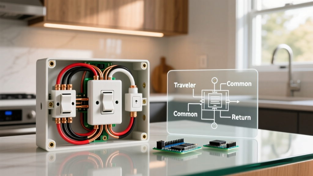
Before unboxing your new hardware, you must understand the baseline architecture of your existing circuit. A standard 3-way setup consists of two SPDT switches connected by a 14/3 or 12/3 Romex cable (depending on whether the circuit is 15-amp or 20-amp).
- Line (Hot): The continuous power source from the breaker panel, typically a black wire.
- Load: The wire carrying power to the light fixture.
- Travelers: Two wires (usually red and black, or red and white) that carry the current between the two switches based on their physical toggle positions.
- Ground: Bare copper or green wire for fault protection.
Critical E-E-A-T Insight: Mechanical 3-way switches do not require a neutral wire to function because they simply bridge the hot and traveler wires. Smart switches, however, contain internal radios and processors that require a continuous 120V circuit (Line to Neutral) to stay powered, even when the light is turned off.
The Neutral Wire Bottleneck in Older Homes
The most common point of failure in DIY three way electrical switch wiring upgrades is the absence of a neutral wire in the switch box. Homes built before the mid-1980s often routed the neutral directly to the light fixture, bypassing the switch boxes entirely. If you open your switch box and only see black, red, white (used as a traveler), and bare copper wires, you lack a dedicated neutral.
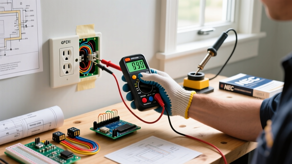
How to verify: Use a non-contact voltage tester (like the Klein Tools NCVT-3) and a multimeter (such as the Fluke 117). Measure the voltage between the suspected neutral bundle (usually a group of white wires wire-nutted together in the back of the box) and the ground wire. A reading of ~120V confirms a usable neutral. Warning: The single white wire connected to the brass screw on your old mechanical switch is almost certainly a traveler wire, not a neutral. Per NEC Article 200.7, white wires used as travelers must be re-identified with black or red electrical tape.
2026 Smart Switch Hardware Comparison Matrix
Selecting the right hardware is contingent upon your existing wiring topology. Below is a comparison of the top-tier 3-way smart switch ecosystems available for residential upgrades.
| Brand & Model | Protocol | Neutral Required? | Companion Switch Type | Avg. Price (2026) |
|---|---|---|---|---|
| Lutron Caséta PD-5S-DV | Clear Connect RF | No (with Pico setup) | Wireless Pico Remote | $65 - $75 |
| Kasa Smart KS230 | Wi-Fi (2.4GHz) | Yes | Wired 3-Way Add-on | $35 - $45 |
| Leviton Decora DW3HL | Wi-Fi / Thread | Yes | Standard Mechanical 3-Way | $55 - $65 |
| GE Cync (No-Neutral) | Bluetooth / Wi-Fi | No (requires bulb) | Wireless or Wired Add-on | $40 - $50 |
Step-by-Step Replacement Protocol: The Lutron Caséta Method
For this guide, we will detail the upgrade process using the Lutron Caséta system, as it represents the gold standard for overcoming the missing-neutral dilemma by utilizing a wireless Pico remote at the secondary switch location. This method eliminates the need to fish new 14/2 cables through finished drywall.
Phase 1: Safety Lockout and Verification
- Kill the Power: Turn off the corresponding 15A or 20A breaker at the main panel. Follow OSHA electrical safety guidelines by applying a physical lockout/tagout device to the breaker to prevent accidental re-energization.
- Verify Zero Voltage: Test both switches with a multimeter. Place one probe on the Line/Traveler terminal and the other on the ground. A reading of 0.0V confirms the circuit is dead.
Phase 2: Primary Switch Wiring (Line/Load Box)
- Identify the Box: Determine which switch box contains the Line (incoming power) or Load (outgoing to fixture). You can only install the main smart dimmer in a box that contains either the Line or the Load, plus the travelers.
- Disconnect Legacy Switch: Remove the old SPDT switch. Cap the traveler wires temporarily.
- Wire the Smart Dimmer: Connect the Lutron PD-5S-DV black wire to the Line (or Load), and the blue wire to the Load (or Line). Connect the green wire to the bare copper ground bundle.
- Manage Travelers: In this wireless companion setup, the traveler wires are no longer needed to carry current to a second mechanical switch. However, if the traveler cable continues to the light fixture, you must splice the travelers together using Wago 221 lever-nuts to maintain the circuit path, or cap them individually if they are dead-ended.
Phase 3: Secondary Switch Conversion (Traveler Box)
- Remove the Second Switch: Disconnect the mechanical switch at the other end of the hallway/stairs.
- Splice the Travelers: Connect the two traveler wires together using a wire nut or lever connector. This effectively bypasses the secondary box, sending continuous hot power to the primary smart switch.
- Cap the Line/Load: Safely cap the remaining hot wire in this box.
- Install the Pico Remote: Mount the Lutron Pico wallplate bracket over the gang box and snap the battery-powered Pico remote into place. The physical upgrade is now complete.
Advanced Troubleshooting & Edge Cases
Even with meticulous three way electrical switch wiring, solid-state switches interact differently with modern LED drivers than mechanical switches do. Be prepared to address these common failure modes:
- LED Ghosting or Flickering: Smart dimmers leak a tiny amount of current (ghost voltage) to power their internal radios. When paired with low-wattage LED bulbs, this can cause flickering or a faint glow when the switch is off. Solution: Install a LUT-MLC capacitor across the hot and neutral wires at the light fixture (not at the switch) to absorb the leakage current.
- Breaker Tripping Upon Installation: This almost always indicates a short circuit caused by misidentifying the ground wire as a neutral, or allowing a bare copper ground to touch the brass traveler terminal. Double-check your wire stripping lengths; 1/2 inch of exposed copper is the maximum standard for most smart switch terminal screws.
- Wi-Fi Dropouts on Kasa/Leviton Switches: If you opted for a Wi-Fi-based 3-way switch and it frequently drops offline, the issue is likely 2.4GHz network congestion or a metal gang box acting as a Faraday cage. Replace metal boxes with PVC old-work boxes, or switch to a hub-based RF system like Lutron or Zigbee.
NEC Compliance and Safety Standards
When performing any electrical upgrade, adherence to the National Electrical Code (NEC) is non-negotiable. The National Fire Protection Association (NFPA) mandates strict rules regarding wire identification, box fill capacity, and grounding.
Under NEC Article 404.2(C), if you are installing a smart switch that requires a neutral wire, and your existing box lacks one, you are legally required to pull a new cable with a neutral conductor rather than improperly borrowing a neutral from an adjacent, unrelated circuit. Furthermore, ensure your gang box has adequate cubic inch volume. Smart switches are significantly deeper (often 1.5 to 1.75 inches) than mechanical toggles. If your wires are being crushed to fit the device, upgrade to a deep 2.5-inch gang box to prevent insulation damage and overheating. By respecting the physics of solid-state relays and adhering to modern code requirements, your 3-way switch upgrade will deliver seamless, safe, and intelligent lighting control for years to come.