
The Hidden Risks of Skipping Pre-Installation Inspections
Learning how to add an electrical outlet is often reduced to a simple tutorial on stripping wires and tightening screws. However, from an inspection and testing perspective, adding a receptacle is a critical intervention in your home's electrical ecosystem. Failing to inspect the existing circuit capacity or verify the new installation with precision testing equipment leads to tripped breakers, melted neutral lugs, or failed municipal inspections. According to the U.S. Consumer Product Safety Commission (CPSC), faulty receptacles and overloaded branch circuits are leading contributors to residential electrical fires.
This guide bypasses basic wiring diagrams and focuses entirely on the inspection, code-compliance, and testing protocols required when adding a new 120V duplex receptacle in the 2026 NEC adoption cycle.
Phase 1: Circuit Capacity and Load Inspection
Before cutting into drywall or fishing new Romex, you must inspect the host circuit. Adding an outlet to an already burdened 15-amp kitchen or living room circuit is a code violation and a fire hazard.
Calculating the 80% Continuous Load Rule
Under NEC Article 210.20, branch circuits supplying continuous loads (those expected to run for 3 hours or more) must be derated to 80% of the breaker's maximum capacity.
- 15-Amp Circuit (14 AWG Wire): Maximum continuous load is 12 Amps (1,440 Watts at 120V).
- 20-Amp Circuit (12 AWG Wire): Maximum continuous load is 16 Amps (1,920 Watts at 120V).
Inspection Action: Use a clamp meter (like the Fluke 323 True-RMS) at the breaker panel to measure the existing amperage draw on the target circuit. If a 15A circuit is already pulling 10A from existing lighting and electronics, adding a new outlet that could theoretically host a 1,500W space heater (12.5A) will guarantee nuisance tripping and potential thermal degradation of the breaker.
Phase 2: NEC-Compliant Component Selection
Municipal inspectors will immediately fail an installation if the receptacle does not match the environmental and code requirements of the space. The current NEC cycle mandates Tamper-Resistant (TR) receptacles in nearly all indoor residential spaces (NEC 406.12), and Weather-Resistant (WR) ratings for damp/outdoor locations.
| Receptacle Type | Recommended Model (2026) | Avg. Cost | Required Application (NEC) |
|---|---|---|---|
| Standard TR Duplex | Leviton T5320-W (15A) | $3.50 - $4.25 | Living rooms, bedrooms, hallways |
| Weather-Resistant (WR) | Hubbell WR20 (20A) | $7.00 - $9.50 | Patios, exterior walls, damp zones |
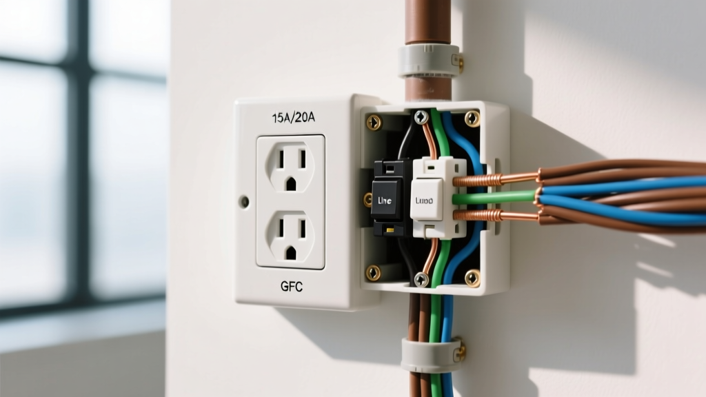
| GFCI Protected | Leviton GFNT1-W (15A) | $16.00 - $19.00 | Bathrooms, kitchens, garages, outdoors |
| AFCI / Dual Function | Leviton AGTR1-W (15A) | $32.00 - $38.00 | Bedrooms, living areas (where panel AFCI is absent) |
Inspector's Note on Box Fill: When adding an outlet, ensure the existing electrical box has adequate cubic inch capacity. A standard single-gang box (18 cu. in.) is required for a single 12 AWG receptacle with multiple cable clamps and grounds. Upgrading to a deep box like the Carlon B618R (22 cu. in.) prevents wire crushing, which can nick insulation and cause ground faults.
Phase 3: Termination and Torque Verification
The most common failure point in DIY outlet installations is the mechanical termination. 'Backstabbing' (pushing wires into the rear spring-loaded holes) is universally condemned by master electricians and inspectors due to high-resistance connection points that arc under load.
The NEC 110.14(D) Torque Requirement
Modern electrical codes require that terminations be tightened to the manufacturer's specified torque. For standard 15A and 20A Leviton and Hubbell receptacles, the side-wiring terminal screws require between 12 and 14 inch-pounds (in-lbs) of torque.
Testing Tool: Do not guess with a standard screwdriver. Use a calibrated torque screwdriver, such as the Klein Tools 32500 or the Ideal Industries Torque Screwdriver. Under-tightening causes arcing and heat; over-tightening strips the brass threads or shears the wire.
Phase 4: Post-Installation Testing Matrix
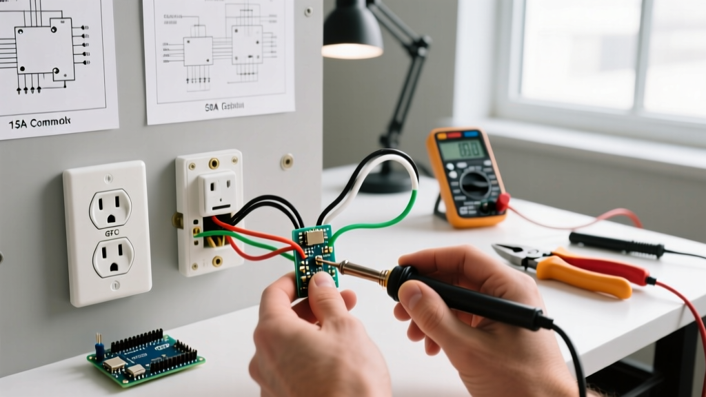
Once the outlet is wired and the breaker is restored, you must verify the installation. While a standard 3-light neon tester is common, it cannot detect high-resistance neutrals or phantom voltages. For a true inspection-grade verification, use a digital multimeter (DMM) alongside a solenoid tester or advanced receptacle analyzer like the Klein Tools RT250.
Verification Checklist & Expected Readings
- Hot to Neutral (H-N): 118V - 122V (Verifies correct line voltage and low-resistance neutral path).
- Hot to Ground (H-G): 118V - 122V (Confirms equipment grounding conductor is bonded and intact).
- Neutral to Ground (N-G): 0V - 2V (Any reading above 3V indicates a loose neutral somewhere upstream or an illegal neutral-ground bond at the receptacle).
- GFCI Trip Test (if applicable): A Class A GFCI must trip between 4mA and 6mA of ground fault leakage. The Klein RT250 will inject a test current and display the exact trip time in milliseconds.
Common Failure Modes & Troubleshooting Matrix
If your post-installation testing reveals anomalies, consult this diagnostic matrix before calling for a municipal final inspection.
| Tester Symptom | Root Cause | Inspection & Fix Protocol |
|---|---|---|
| Open Neutral | Neutral wire disconnected upstream or loose terminal screw. | Inspect all upstream daisy-chained neutrals. Re-terminate using side-wiring and torque to 14 in-lbs. |
| Open Ground | Missing equipment ground or broken ground pigtail. | Verify bare copper ground is pigtailed to the green screw and the metal box (if applicable). |
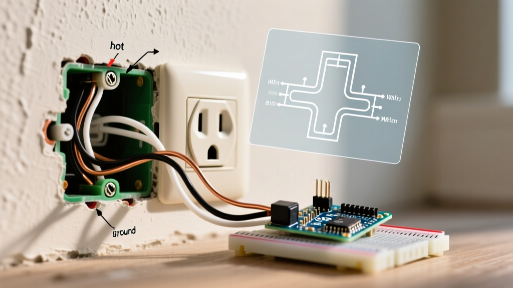
| Hot/Neutral Reversed | Black (hot) wire on silver screw; White (neutral) on brass screw. | Immediate shock hazard. Swap wires. Brass is for Black (Hot), Silver is for White (Neutral). |
| High N-G Voltage (>5V) | Shared neutral overload or loose neutral bus bar connection. | Inspect panel neutral bar. Check for multi-wire branch circuit (MWBC) handle tie issues. |
Passing the Municipal Final Inspection
When the local Authority Having Jurisdiction (AHJ) arrives to inspect your newly added outlet, they will look beyond the wiring. Ensure your installation passes the visual and physical inspection criteria outlined by the National Fire Protection Association (NFPA 70):
- Receptacle Spacing (NEC 210.52): No point along a continuous wall line can be more than 6 feet from an outlet. Walls 2 feet or wider require a receptacle.
- Faceplate Fit: The cover plate must sit flush against the wall. If the drywall cutout was too large, use a jumbo faceplate or a plaster ring extender; inspectors will fail gaps that expose the interior of the box.
- GFCI Labeling: If the new outlet is protected by a GFCI breaker or an upstream GFCI receptacle, you must apply the included 'GFCI Protected / No Equipment Ground' or standard 'GFCI Protected' sticker to the faceplate.
- Fire Caulking: If the outlet was added on an exterior wall or a fire-rated separation wall (like an attached garage), the inspector will check for fire-rated expanding foam or caulk sealing the cable penetrations to maintain the wall's fire-resistance rating, a standard heavily enforced by OSHA and local building codes.
By treating the addition of a simple electrical outlet as a rigorous process of load inspection, precision termination, and multimeter verification, you ensure a safe, code-compliant installation that will pass inspection on the first visit and operate safely for decades.