
Decoding the Electrical Wiring Socket Diagram for Safe Installation
Installing a standard duplex receptacle is a foundational DIY electrical task, but it demands strict adherence to safety codes and precise physical execution. Before you strip a single wire, you must understand how to read an electrical wiring socket diagram. This visual blueprint dictates the exact routing of the hot, neutral, and ground conductors to their respective terminals, ensuring your circuit operates safely and passes inspection.
In 2026, the adoption of the latest National Electrical Code (NEC) standards means that simply twisting wires onto screws is no longer acceptable. Modern installations require tamper-resistant (TR) receptacles, precise wire stripping lengths, and calibrated torque terminations. This guide will walk you through the exact steps to install a 15-amp or 20-amp spec-grade receptacle, utilizing the diagram as your primary reference.
Anatomy of a Standard Electrical Wiring Socket Diagram
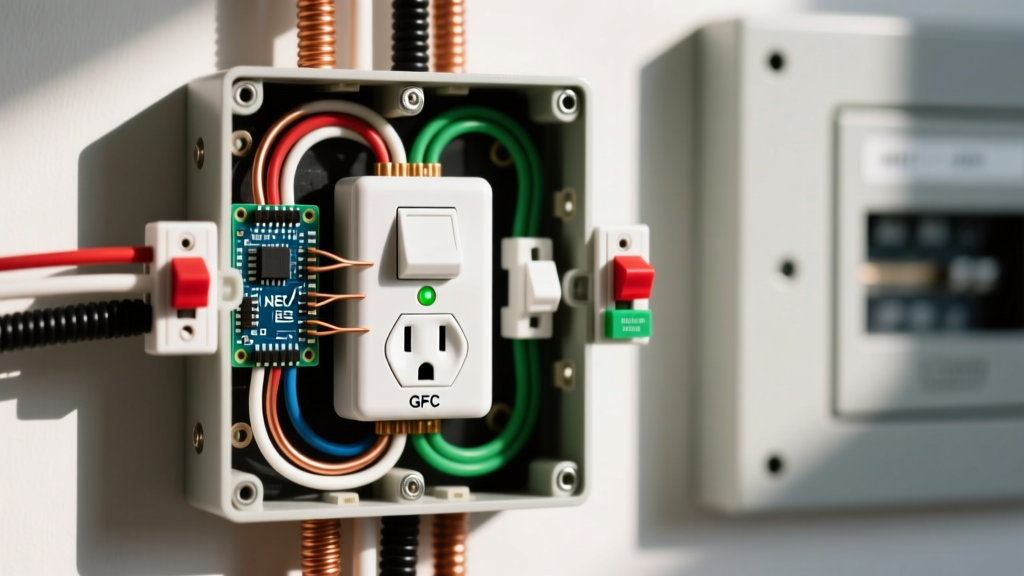
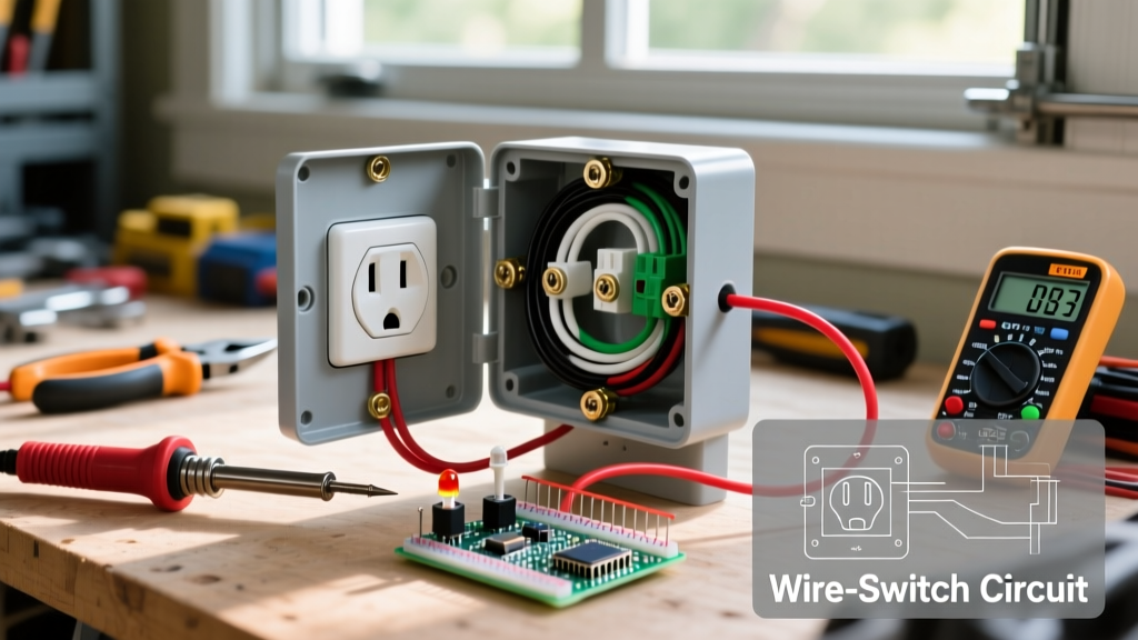
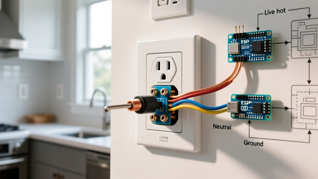
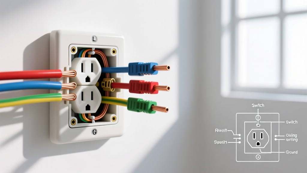
When you look at a standard electrical wiring socket diagram, you will notice three distinct termination zones on the back and sides of the receptacle yoke. Understanding these zones is critical for preventing reversed polarity and ground faults.
- Brass Terminals (Hot/Line): These screws connect to the black (or red) insulated wire. They carry the 120V alternating current from the breaker panel. On a diagram, this is typically labeled 'L' or 'Hot'.
- Silver Terminals (Neutral): These screws connect to the white insulated wire. This completes the circuit back to the panel. Diagrams label this 'N' or 'Neutral'. The silver screw is physically longer than the brass screw to accommodate the return path.
- Green Terminal (Ground): This connects to the bare copper or green insulated wire. It provides a safe path for fault currents, tripping the breaker in the event of a short. Diagrams label this 'G' or 'Ground'.
NEC Code Alert: According to NEC Article 406.12, all 15-amp and 20-amp, 125-volt and 250-volt non-locking receptacles installed in dwelling units must be Tamper-Resistant (TR). Always verify the 'TR' stamp on the yoke of your new receptacle before installation.
Tools and Materials Required
Professional-grade results require professional-grade tools. Do not rely on cheap, uncalibrated hardware store tools for electrical terminations.
- Receptacle: Leviton T5262 (15A TR Spec-Grade, approx. $3.50) or Hubbell HBL5262 (20A TR Spec-Grade, approx. $5.50).
- Voltage Tester: Fluke 117 True-RMS Digital Multimeter or a Klein Tools NCVT-3 non-contact voltage tester.
- Wire Strippers: Klein Tools 11055 (for 10-18 AWG solid/stranded wire).
- Torque Screwdriver: CDI 401SM (10-50 in-lbs) to meet NEC 110.14(D) torque requirements.
- Screwdrivers: Klein Tools 32308 Multi-bit Stubby screwdriver (includes #2 Phillips and 1/4-inch slotted).
Step-by-Step Installation Guide
Step 1: De-energize and Verify the Circuit
Navigate to your main electrical panel and switch off the breaker controlling the room you are working in. Use your Fluke 117 multimeter to test between the hot and neutral slots, and then hot to ground, of the existing receptacle. The reading must be exactly 0.0V. Never assume a wire is dead based solely on the breaker position; always verify with a meter.
Step 2: Prepare the Conductors
Remove the existing receptacle. Inspect the wire insulation for cracks or heat damage. If the wire ends are pitted or deeply grooved from previous terminations, snip them back. Using your Klein Tools 11055 strippers, strip exactly 3/4-inch (19mm) of insulation from the black, white, and ground wires. Pro Tip: Use the physical strip gauge molded into the back of your new Leviton or Hubbell receptacle to verify the exact length. Exposed copper outside the terminal pad is a severe shock and arc-flash hazard.
Step 3: Follow the Electrical Wiring Socket Diagram for Terminations
You have two choices for termination: side-wiring (screw loops) or back-wiring (screw-clamp). For 12 AWG wire on 20A circuits, back-wiring using the internal screw-clamp plates is highly recommended as it provides a larger surface area contact and superior pull-out resistance.
- Ground First: Form a J-hook with the bare copper wire and loop it clockwise around the green ground screw. Tighten to 14 in-lbs using your torque screwdriver.
- Neutral Second: Insert the stripped white wire into the back-wire hole adjacent to the silver screw, or loop it clockwise around the silver screw. Tighten to 14 in-lbs.
- Hot Last: Insert the black wire into the back-wire hole adjacent to the brass screw, or loop it clockwise. Tighten to 14 in-lbs.
Step 4: Pigtailing Neutrals (Multi-Wire & Daisy Chains)
If your electrical wiring socket diagram shows multiple cables entering the box (a daisy-chain setup), do not use the receptacle's internal brass/silver straps to carry the neutral current to the next downstream outlet. NEC 300.13(B) requires the neutral continuity to be independent of the device. You must use a wire nut (or Wago 221-413 lever connector) to pigtail the white wires together, with a single pigtail running to the receptacle's silver terminal.
Step 5: Box Dressing and Securing
Carefully fold the wires into the back of the single-gang or double-gang box. Push the ground wires in first, followed by the neutrals, and finally the hots. This prevents the ground wires from being pinched against the metal box or the hot terminals. Seat the receptacle yoke flush against the drywall or plaster ring, and secure it using the provided #6-32 mounting screws. Do not overtighten, as this can crack the thermoplastic face.
15-Amp vs. 20-Amp Receptacle Wiring Specifications
Choosing the correct receptacle and wire gauge is dictated by the breaker size. Refer to this matrix to ensure your installation matches the circuit capacity.
| Specification | 15-Amp Circuit | 20-Amp Circuit |
|---|---|---|
| Breaker Size | 15A (Standard) | 20A (Standard) |
| Minimum Wire Gauge | 14 AWG Copper | 12 AWG Copper |
| Receptacle NEMA Config | 5-15R (Two parallel slots) | 5-20R (One T-shaped slot) |
| Allowed Receptacle Ratings | 15A only | 15A or 20A |
| Terminal Torque Spec | 14 in-lbs (Typical) | 14 in-lbs (Typical) |
Note: You can install a 15A receptacle on a 20A circuit (provided there is more than one receptacle on the circuit, per NEC 210.21(B)(3)), but you can never install a 20A receptacle on a 15A circuit with 14 AWG wire.
Common Edge Cases and Troubleshooting
Split-Wired Receptacles (Half-Hot)
If your electrical wiring socket diagram indicates a split-wired setup (where the top plug is controlled by a wall switch and the bottom is always hot), you must break the brass fin on the side of the receptacle. Use needle-nose pliers to snap the small brass tab connecting the top and bottom brass screws. Do not break the silver fin; the neutral must remain shared for both halves.
Multi-Wire Branch Circuits (MWBC)
If you open the box and find two hot wires (one black, one red) connected to different phases sharing a single white neutral, you are dealing with an MWBC. The NEC requires these to be on a double-pole breaker or equipped with a handle tie (NEC 210.4). When wiring the socket, you must pigtail the hot wires to separate receptacles or ensure the split-wire fin is removed and each hot connects to its respective brass screw.
Bootleg Grounds
In older homes, you might find a jumper wire connecting the neutral silver screw to the green ground screw. This is a dangerous 'bootleg ground' designed to trick older receptacle testers. It creates a severe shock hazard if the neutral wire ever disconnects upstream, energizing the metal chassis of any plugged-in appliance. Remove the jumper immediately and install a proper GFCI receptacle if a true ground wire is not present in the box, labeling it 'No Equipment Ground' as permitted by NEC 406.4(D)(2).
Final Testing and Safety Verification
Once the cover plate is installed and the breaker is turned back on, use a standard 3-light receptacle tester (like the Gardner Bender GRT-13) to verify the wiring. You should see two yellow lights indicating 'Correct'. If you see a red and yellow light, you have reversed polarity (hot and neutral swapped). If you see only one yellow light, you have an open ground. Turn the power back off and correct any errors immediately.
For further reading on residential electrical safety and tamper-resistant requirements, consult the Electrical Safety Foundation International (ESFI). Additionally, the complete National Electrical Code standards can be reviewed via the National Fire Protection Association (NFPA). Always check with your local building department, as local amendments may supersede national codes. For general home electrical safety guidelines, refer to the U.S. Consumer Product Safety Commission (CPSC).