
Understanding the Wiring Diagram for GFCI Outlet Installations
Interpreting a wiring diagram for gfci outlet configurations is the most critical skill for any DIYer or apprentice electrician working in wet or damp locations. Unlike standard duplex receptacles, Ground Fault Circuit Interrupter (GFCI) outlets contain internal microprocessors that monitor current imbalances as small as 4 to 6 milliamps. As we navigate the 2026 National Electrical Code (NEC) cycle, GFCI protection requirements have expanded aggressively, now mandating protection for nearly all 125-volt and 250-volt receptacles up to 50 amps in kitchens, laundry areas, garages, and crawl spaces.
According to the Electrical Safety Foundation International (ESFI), GFCIs have prevented thousands of electrocutions over the last four decades. However, improper wiring—specifically confusing the LINE and LOAD terminals—renders the downstream protection useless and creates a severe shock hazard. This guide breaks down the exact anatomy, tools, and step-by-step installation procedures required for a code-compliant GFCI installation.
Anatomy of a GFCI Receptacle: Line vs. Load
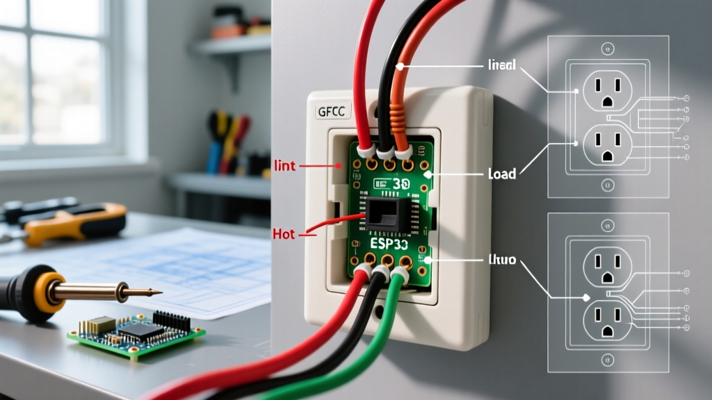
Before stripping a single wire, you must understand the terminal layout found on the back of the device. A standard GFCI (such as the widely used Leviton GFNT2-W Slim GFCI) features four primary screw terminals and one grounding screw, divided into two distinct zones:
- LINE Terminals (Brass & Silver): These connect to the incoming power directly from the electrical panel. The brass screw is for the ungrounded conductor (Hot/Black), and the silver screw is for the grounded conductor (Neutral/White).
- LOAD Terminals (Brass & Silver with Tape): These are used only if you intend to protect downstream standard outlets. They feed power to the next device in the circuit while extending the GFCI's ground-fault monitoring.
- Grounding Terminal (Green): Connects to the bare copper or green insulated equipment grounding conductor.
Expert Warning: The most common failure mode in DIY GFCI wiring is connecting the incoming panel power to the LOAD terminals. If wired backward, the GFCI will power on and reset, but it will not provide ground-fault protection, and the internal test button will fail to trip the device.
Essential Tools for 2026 Code Compliance
Modern electrical codes strictly enforce torque specifications and wire preparation standards. To ensure your installation passes inspection and operates safely, assemble the following professional-grade tools:
| Tool / Material | Recommended Model | Est. Cost (2026) | Purpose |
|---|---|---|---|
| Slim GFCI Receptacle | Leviton GFNT2-W | $18.50 | Fits easily in shallow or crowded junction boxes. |
| Wire Strippers | Klein Tools 11055 | $28.00 | Precise stripping for 14 AWG and 12 AWG solid copper. |
| Torque Screwdriver | Klein Tools 32500 | $35.00 | Required by NEC 110.14(D) to achieve exact terminal torque. |
| NCVT Tester | Milwaukee 2202-20 | $25.00 | Initial verification of de-energized circuits. |
| Digital Multimeter | Fluke 117 | $210.00 | Definitive LINE vs. LOAD identification and voltage testing. |
Step-by-Step GFCI Installation Guide
Step 1: De-Energize and Verify (LOTO)
Turn off the corresponding 15A or 20A breaker at the main service panel. Use your Milwaukee NCVT to verify the absence of voltage at the outlet. Follow up with a Fluke 117 multimeter, testing Hot-to-Neutral, Hot-to-Ground, and Neutral-to-Ground to confirm 0.0V. Treat every conductor as live until proven otherwise.
Step 2: Identify LINE vs. LOAD Conductors
If you are replacing an existing GFCI or working in a multi-outlet box, you may have multiple cables. Before disconnecting the old device, use a non-contact tester or multimeter to identify which cable brings power from the panel (LINE) and which leaves to feed other outlets (LOAD). Mark the LINE cable's wires with black electrical tape to prevent confusion.
Step 3: Prepare the Conductors
Using your Klein 11055 strippers, strip exactly 3/4 inch5/8 inch for 14 AWG wire. Do not nick the copper conductor, as this creates a hot spot and potential failure point under load. If the wire is heavily oxidized or previously kinked, snip the end and re-strip.
Step 4: Terminate the Ground
Always connect the equipment grounding conductor first. If you have a downstream cable that also requires grounding, use a wire nut to pigtail both bare copper wires together with a 6-inch green or bare copper jumper wire, then connect the jumper to the green grounding screw on the GFCI.
Step 5: Wire the LINE Terminals
Connect the incoming Hot (Black) wire to the brass LINE screw and the incoming Neutral (White) wire to the silver LINE screw. Ensure the wire loops clockwise around the screw so that tightening the screw pulls the loop closed rather than pushing it out. No bare copper should be visible outside the terminal clamp.
Step 6: Wire the LOAD Terminals (If Applicable)
If your wiring diagram dictates downstream protection, connect the outgoing Hot wire to the brass LOAD screw and the outgoing Neutral wire to the silver LOAD screw. If you are only protecting this single location (Line-Only configuration), leave the LOAD terminals completely empty and retain the yellow warning tape over them.
Step 7: Torque to Manufacturer Specifications
The NEC mandates that terminals be tightened to the manufacturer's specified torque. For the Leviton GFNT2-W, the required torque for 12 AWG copper is 14 in-lbs. Set your Klein torque screwdriver and tighten until it clicks. This prevents thermal expansion and contraction from loosening the connection over time, which is a leading cause of electrical fires.
Wiring Scenarios: Line-Only vs. Line-and-Load
Choosing the correct wiring diagram for your GFCI outlet depends entirely on your circuit topology and local code requirements.
| Configuration | Wiring Method | Use Case | Pros & Cons |
|---|---|---|---|
| Line-Only (Single Location) | Panel power connects to LINE. LOAD is unused. | When the GFCI is the last outlet on the run, or downstream outlets are already protected by a GFCI breaker. | Pro: Simple, fewer failure points. Con: Does not protect downstream standard receptacles. |
| Line-and-Load (Multiple Location) | Panel power to LINE; downstream cable to LOAD. | When a single GFCI must protect standard outlets further down the circuit (e.g., kitchen backsplash). | Pro: Cost-effective (one GFCI protects multiple devices). Con: A ground fault anywhere downstream trips the main GFCI, requiring you to hunt for the fault location. |
Advanced Troubleshooting and Edge Cases
Even with a perfect wiring diagram for GFCI outlet setups, complex residential wiring can introduce edge cases that cause immediate tripping or failure to reset.
The Shared Neutral (MWBC) Problem
Multi-Wire Branch Circuits (MWBC) use two hot wires (usually on a 240V double-pole breaker) sharing a single neutral wire to save copper. You cannot install a standard receptacle-style GFCI on an MWBC if the neutral is shared downstream of the device. The GFCI will detect the returning current from the second hot leg as a ground fault and trip instantly. Solution: Pigtail the neutrals before the GFCI (if code allows in your specific scenario), or replace the standard breaker with a 2-pole GFCI circuit breaker at the panel.
Bootleg Grounds and False Positives
In older homes, a previous owner may have wired a jumper between the neutral and ground terminals on a standard outlet to trick a 3-prong tester. When you install a GFCI and push the test button, the internal circuitry routes current from Hot to Ground to simulate a fault. If there is no true path to earth (a bootleg ground), the GFCI will not trip during testing, or it will behave erratically. Always verify a true ground path back to the panel using a multimeter measuring Hot-to-Ground (should read ~120V).
Neutral-to-Ground Bonding Downstream
If a downstream outlet wired to the LOAD terminals has its neutral and ground bars touching (or a wire pinched between the device and the metal box), the GFCI will trip the moment a load is applied to the downstream outlet. The GFCI sees the neutral current splitting between the neutral wire and the ground wire, interpreting it as a leakage fault.
Final Inspection and Testing
Once the device is secured in the junction box and the faceplate is installed, restore power at the panel. The GFCI should be in the 'Reset' state. Press the built-in 'Test' button; you should hear a sharp mechanical click, and the 'Reset' button should pop out, cutting power. Use a plug-in GFCI tester (like the Gardner Bender GFI-3501) at the GFCI and all downstream LOAD-protected outlets to verify correct wiring and tripping functionality. For comprehensive safety standards regarding ground-fault protection in construction and residential environments, always consult OSHA Standard 1926.404 and the latest NFPA 70 National Electrical Code.