
Mastering the Socket Cat 6 Wiring Diagram for Wall Plates
As smart homes and Wi-Fi 7 access points become standard in 2026, the demand for reliable, high-bandwidth hardwired connections has never been higher. While wireless tech advances, the backbone of any robust network remains the physical copper infrastructure. When terminating these runs, understanding the socket cat 6 wiring diagram for wall plates is the critical bridge between a gigabit-capable network and a frustrating bottleneck. In networking terminology, the "socket" refers to the RJ45 keystone jack that snaps into your wall plate. Getting the pinout and termination geometry right ensures your network supports 10GBASE-T speeds up to 55 meters.
This guide breaks down the exact wiring diagrams, physical scenarios, and termination tolerances required for professional-grade Cat 6 wall plate installations.
The Core Blueprint: T568A vs. T568B Pinout Standards
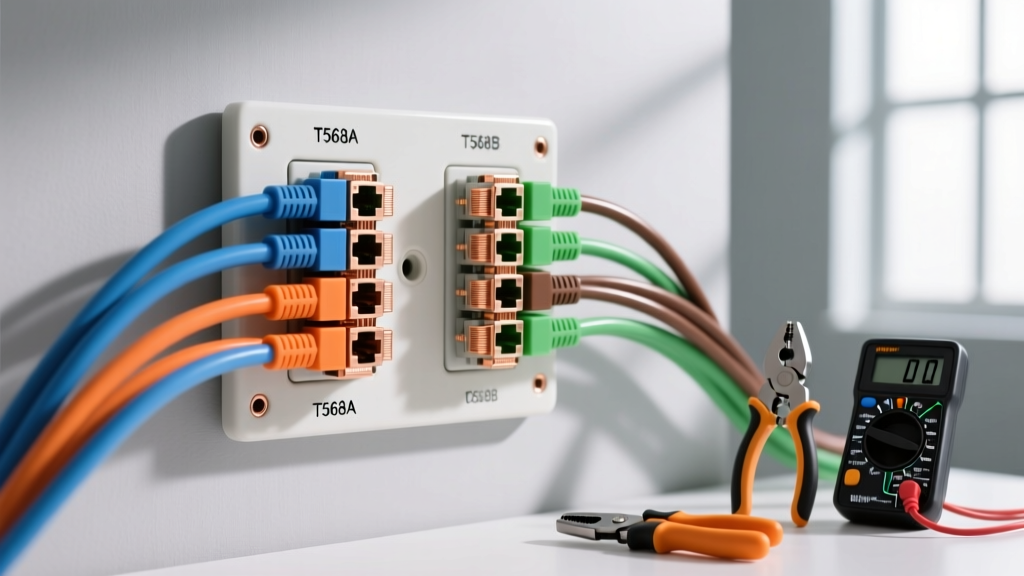
Before touching a punch-down tool, you must choose a wiring standard. The ANSI/TIA-568 standard, maintained by the Telecommunications Industry Association, defines two acceptable pinout schemes: T568A and T568B. Both perform identically, but mixing them on the same cable run creates a crossover cable, which will cause link failures on modern auto-MDIX switches.
Pro-Tip for 2026 Installations: T568B remains the dominant standard for commercial and residential retrofits in North America. Unless your local building code or existing infrastructure explicitly mandates T568A, default to T568B for all socket terminations to maintain consistency.
Cat 6 Keystone Jack Pinout Matrix (T568B)
Most modern keystone jacks (like the Leviton QuickPort or Panduit Mini-Com) feature color-coded IDC (Insulation Displacement Contact) towers. Here is the exact mapping you will follow when reading the diagram printed on the side of the socket:
| Pin # | Wire Color (T568B) | Function (10GBASE-T) | Pair Number |
|---|---|---|---|
| 1 | White-Orange | BI_DA+ / TX+ | Pair 2 |
| 2 | Orange | BI_DA- / TX- | Pair 2 |
| 3 | White-Green | BI_DB+ / RX+ | Pair 3 |
| 4 | Blue | BI_DC+ | Pair 1 |
| 5 | White-Blue | BI_DC- | Pair 1 |
| 6 | Green | BI_DB- / RX- | Pair 3 |
| 7 | White-Brown | BI_DD+ | Pair 4 |
| 8 | Brown | BI_DD- | Pair 4 |
Scenario 1: New Construction & Open-Stud Rough-Ins
When walls are open, installing a socket cat 6 wiring diagram for wall plates is straightforward, provided you respect low-voltage bend radius rules. Cat 6 cable features a central plastic spline (cross-separator) that maintains pair isolation. Crushing this spline ruins the cable's geometry and causes Near-End Crosstalk (NEXT).
Hardware & Mounting Specifics
- Mounting Bracket: Use a low-voltage mud ring (e.g., Carlon SC100RR 1-Gang Non-Metallic Old Work Bracket). Do not use standard deep electrical boxes; they encourage tight, damaging cable bends.
- Securing the Cable: Use Velcro straps or specialized wide-crown staples (like the Gardner Bender GS-1018). Never use standard Romex staples, which will crush the 23AWG conductors.
- Slack Loop: Leave exactly 12 to 18 inches of service loop inside the wall cavity for future re-termination.
Scenario 2: Retrofitting Existing 1-Gang Electrical Boxes
The most common DIY scenario involves fishing Cat 6 through finished walls into an existing 1-gang electrical box that previously held a coaxial or telephone outlet. This scenario presents severe spatial constraints.
- Remove the Yoke: Standard keystone jacks have a metal or plastic yoke (mounting strap). Snap this yoke off the keystone module so it can sit deeper inside a crowded 1-gang box.
- Manage the Bend Radius: The TIA-568 standard mandates a bend radius of no less than 4 times the cable diameter (approx. 1 inch for Cat 6). If the box is packed with Romex, you must use a shallow-profile keystone jack, such as the Panduit Mini-Com series, which reduces the rear footprint by 30%.
- Isolate from High Voltage: If sharing a dual-gang box with 120V AC power, a physical UL-listed divider plate must be installed between the high-voltage and low-voltage sides to prevent EMI (Electromagnetic Interference) and meet NEC Article 800.133 safety codes.
Step-by-Step Termination: Executing the Diagram
Reading the diagram is only half the battle; the physical execution dictates your signal integrity. In 2026, bare copper 23AWG Cat 6 CMP (Plenum) cable costs between $220 and $280 per 1,000-foot spool. Do not ruin a $250 spool with improper termination.
The 13mm Untwist Rule
The twists in Cat 6 cable are engineered to cancel out electromagnetic interference. When mapping the wires to the IDC towers on your socket diagram, do not untwist the pairs more than 0.5 inches (13mm). Untwisting beyond this threshold immediately degrades the cable from Cat 6 to Cat 5e performance levels, causing failed certification tests.
Punch-Down Execution
- Strip back the outer jacket exactly 1.5 inches using a dedicated jacket stripper (avoid ring-style strippers that nick the copper).
- Fold the spline back and snip it flush with the jacket.
- Seat the wires into the color-coded slots matching the T568B diagram printed on the keystone.
- Use an impact punch-down tool with a 110-style blade (e.g., Klein Tools VDV226-110). Set the impact dial to "High" for 23AWG solid copper.
- Ensure the cutting blade faces the outside of the jack to trim the excess wire flush. If the blade faces inward, you will sever the wire inside the IDC slot, causing an open circuit.
Troubleshooting Matrix: Common Wall Plate Failures
Even with a perfect socket cat 6 wiring diagram, physical installation errors will cause link degradation. Use a basic wire mapper or a Fluke Networks LinkIQ to diagnose these specific failure modes.
| Failure Mode | Root Cause | Corrective Action |
|---|---|---|
| Split Pairs | Wires mapped sequentially (1-8) instead of following the T568B pair geometry (e.g., Pin 3 and 6 are not the Green pair). | Cut off the keystone jack and re-terminate strictly following the color-coded diagram on the socket. |
| High NEXT (Crosstalk) | Untwisting the pairs more than 13mm before seating them into the IDC towers. | Re-terminate, pushing the jacket closer to the tower base to minimize exposed untwisted wire. |
| Open Circuit | Punch-down tool blade faced inward, cutting the wire, or using CCA (Copper Clad Aluminum) cable that snapped under pressure. | Verify blade orientation. Always use a continuity tester before snapping the jack into the wall plate. |
| Return Loss | Cable crushed by tight zip-ties or standard staples behind the wall plate, altering the 100-ohm impedance. | Open the wall plate, relieve the cable tension, and replace crushed sections if the spline is deformed. |
The CCA Warning: A Critical 2026 Procurement Note
When sourcing materials for your wall plate scenarios, beware of CCA (Copper Clad Aluminum) cable flooding online marketplaces. CCA violates UL and BICSI standards for permanent links. Aluminum oxidizes at the IDC punch-down point, leading to high resistance, heat generation, and eventual link failure. Always verify that your cable is stamped with "23AWG Solid Bare Copper" and check the cut end of the wire to ensure the core is silver-colored copper, not white aluminum.
Finalizing the Wall Plate Assembly
Once the socket is terminated and tested, snap the keystone jack into the 6-port or 4-port modular faceplate. Insert the dust shutter (mandatory for commercial spaces to prevent debris accumulation). Finally, secure the faceplate to the mud ring using the provided 6-32 machine screws. Do not overtighten the screws, as this will warp the plastic faceplate and misalign the internal RJ45 contacts, causing intermittent physical disconnects when patch cords are plugged and unplugged.