
Understanding the 6-Prong Round Connector Standard
When towing heavy-duty equipment, horse trailers, or mid-sized travel trailers, the 6-prong round connector is the industry standard for delivering reliable power to lighting, electric brakes, and auxiliary systems. However, misinterpreting a wiring diagram for 6 prong trailer plug configurations is one of the leading causes of trailer brake failure, electrical fires, and blown tow-vehicle alternators. According to the Federal Motor Vehicle Safety Standard (FMVSS) 108, all trailer lighting and braking circuits must maintain strict voltage thresholds and circuit protection to remain street-legal and safe.
Unlike the more common 4-way flat connector, the 6-prong round plug introduces dedicated circuits for electric trailer brakes and a 12-volt auxiliary charge line. This requires a deeper understanding of DC voltage drop, wire gauge sizing, and proper circuit isolation. Below is the definitive safety and code-compliance guide for wiring, maintaining, and troubleshooting your 6-way trailer connector in 2026.
Standard SAE J286 Pinout and Wire Gauge Requirements
The Society of Automotive Engineers (SAE) outlines the standard pinout for 6-way round connectors. Adhering to these color codes and minimum American Wire Gauge (AWG) specifications is critical to prevent voltage drop, which can cause electric trailer brakes to engage weakly or fail entirely on long downhill grades.
| Pin Position | Function | Standard Wire Color | Minimum Wire Gauge (AWG) | Circuit Protection |
|---|---|---|---|---|
| Pin 1 (Top) | Tail / Running Lights | Brown | 14 AWG | 15A Fuse |
| Pin 2 (Right) | Ground Return | White | 10 AWG | N/A |
| Pin 3 (Bottom Right) | Left Turn / Stop | Yellow | 14 AWG | 20A Fuse |
| Pin 4 (Bottom Left) | Right Turn / Stop | Green | 14 AWG | 20A Fuse |
| Pin 5 (Left) | Electric Brakes | Blue | 12 AWG | 40A Breaker |
| Pin 6 (Center) | 12V Auxiliary / Charge | Red or Black | 10 AWG | 30A Breaker |
The 'Center Pin' Controversy: Ground vs. Auxiliary
One of the most dangerous edge cases in trailer wiring is the center pin assignment. While the SAE standard dictates that the center pin (Pin 6) should be the 12V auxiliary charge line and Pin 2 should be the ground, many aftermarket RV manufacturers and horse trailer builders swap these two pins.
CRITICAL SAFETY WARNING: If you wire the center pin as Ground on a trailer that expects 12V Auxiliary, you will create a dead short the moment the tow vehicle's alternator sends charge current through the plug. This will instantly melt the wiring harness and can cause a severe electrical fire. Always verify the tow vehicle's socket pinout with a multimeter before connecting a newly wired trailer.
To resolve this safely, purchase a heavy-duty cast-metal 6-prong plug (such as the Pollak 11-726 or Hopkins 47435, typically priced between $18 and $25). These models feature screw-terminal interiors that allow you to easily swap the White and Red/Black wires if your specific tow vehicle requires a non-standard center-pin ground configuration.
Code Compliance: NFPA 1192 and Breaker Sizing
For recreational vehicles and trailers equipped with living quarters, the NFPA 1192 Standard on Recreational Vehicles dictates strict overcurrent protection rules for DC wiring. You cannot simply run a wire from the trailer plug to the trailer's battery or brake controller without proper circuit protection at the source.
Mandatory Circuit Protection Layout
- Electric Brake Circuit (Blue Wire): Must be protected by a 40-Amp auto-reset circuit breaker mounted within 18 inches of the tow vehicle's battery or the trailer's junction box. This prevents the brake controller from drawing unregulated current in the event of a short.
- 12V Auxiliary Charge (Red/Black Wire): Requires a 30-Amp or 40-Amp auto-reset breaker. This line is used to maintain the trailer's breakaway battery or power interior 12V DC outlets. Without a breaker, a depleted trailer battery can pull over 60 Amps from the tow vehicle's alternator upon initial connection, destroying the alternator diodes.
- Lighting Circuits (Brown, Yellow, Green): Should be fused at the tow vehicle's main fuse panel. If extending wiring on the trailer side, use inline ATC blade fuses rated at 15A to protect against chafed wires shorting against the steel trailer frame.
Step-by-Step Safety Wiring Procedure
Proper physical termination is just as important as the schematic. Vibration and moisture are the enemies of trailer wiring. Follow these steps to ensure a weather-tight, vibration-proof connection.
- Prepare the Jacket: Strip back 2.5 inches of the main trailer cable jacket. Do not nick the copper strands. Use a specialized wire stripping tool like the IWISS SN-28B to ensure clean cuts.
- Apply Heat Shrink: Slide 3/16-inch marine-grade adhesive heat shrink tubing (such as Ancor Marine) over each individual wire before crimping. Standard vinyl electrical tape is a code violation in mobile environments as it unspools under heat and vibration.
- Crimp the Terminals: Use a Delphi Weather Pack crimping tool to attach the solid copper pins to the wires. A proper crimp should pass the 'pull test' (withstanding 15 lbs of pull force without slipping).
- Seal the Connections: Slide the heat shrink over the crimp barrel and apply heat until the adhesive sealant oozes from the edges. This creates an IP67-rated waterproof seal.
- Apply Dielectric Grease: Before mating the plug to the socket, pack the pin cavities with a lithium-based dielectric grease (e.g., Permatex 22058). This displaces moisture and prevents galvanic corrosion between the brass pins and the socket contacts.
- Install the Strain Relief: Ensure the cable clamp at the base of the plug housing is tightened securely over the outer jacket of the cable, not the individual wires. This prevents tension from pulling the pins out of the housing while driving.
Advanced Troubleshooting: Voltage Drop & Ground Loops
Even with a perfect wiring diagram for 6 prong trailer plug setups, real-world degradation occurs. If your trailer brakes feel weak or your running lights flicker, you are likely experiencing voltage drop or a ground loop.
Testing for Voltage Drop
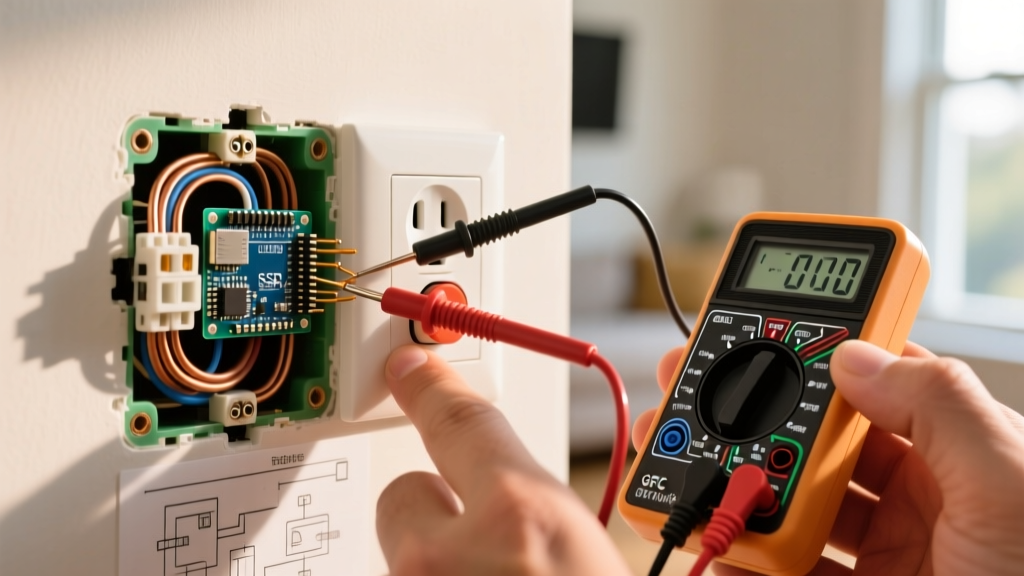
According to guidelines from Penn State Extension's agricultural safety programs, a healthy 12V DC trailer circuit should not experience more than a 0.5-volt drop under load. To test this:
- Set your digital multimeter to DC Volts.
- Connect the positive probe to the 12V Auxiliary pin on the trailer side of the plug.
- Connect the negative probe directly to the trailer's steel frame (bare metal).
- With the tow vehicle running and a load applied (e.g., interior lights turned on), the reading should be above 13.2V. If it reads below 12.5V, you have severe resistance in the ground wire or the charge wire.
Eliminating Ground Loops
A ground loop occurs when the trailer's lights attempt to ground through the hitch ball rather than the dedicated White ground wire. This causes lights to dim when the turn signals are activated. To fix this, run a dedicated 10 AWG White ground wire from the trailer plug directly to a clean, unpainted steel bolt on the trailer tongue. Never rely on the trailer hitch as a primary ground path; the grease and paint on the hitch ball create high electrical resistance.
Frequently Asked Questions (FAQ)
Can I use a 6-prong to 4-prong adapter safely?
Yes, but with limitations. A 6-to-4 adapter will only pass the lighting circuits (Tail, Left, Right, Ground). You will lose the Electric Brake and 12V Auxiliary circuits. Towing a trailer equipped with electric brakes using a 4-way adapter is illegal and highly dangerous, as the trailer brakes will not engage.
Why is my 6-prong plug melting at the center pin?
Melting at the center pin is almost always caused by an undersized wire or a missing circuit breaker on the 12V auxiliary line. If the trailer battery is deeply discharged, it will pull maximum amperage from the tow vehicle. If the wire is only 14 AWG instead of the required 10 AWG, the wire will overheat and melt the plastic housing. Upgrade to 10 AWG and install a 30A breaker immediately.
How often should I reapply dielectric grease?
For trailers stored outdoors or used in marine environments, inspect and reapply dielectric grease every 6 months. For seasonal agricultural or RV use, an annual application before the towing season is sufficient to prevent green copper oxide buildup on the pins.