
Mastering the Basics: Your First Electrical Wiring Light Switch Project
Tackling your first electrical wiring light switch replacement can feel intimidating, but the single-pole switch is the most straightforward circuit in residential wiring. Whether you are upgrading a cracked, yellowed toggle to a modern Decora rocker or replacing a faulty unit, understanding the fundamental physics and National Electrical Code (NEC) requirements is non-negotiable. According to the Electrical Safety Foundation International (ESFI), electrical malfunctions cause over 50,000 home fires annually, many stemming from poor terminations and overloaded circuits. This 2026 guide strips away the fluff, providing you with exact tool models, precise wire preparation measurements, and the professional techniques that licensed electricians use to ensure a safe, arc-free connection.
The Anatomy of a Single-Pole Circuit
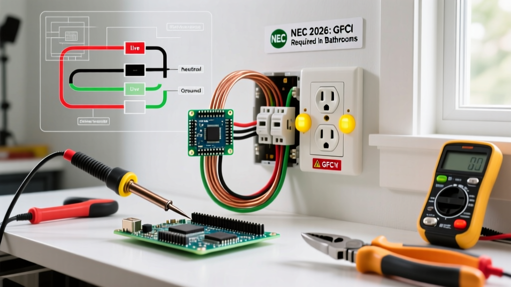
Before touching a screwdriver, you must understand the flow of electricity. A standard single-pole switch acts as a simple gatekeeper on the 'hot' leg of the circuit. It interrupts the ungrounded conductor (hot wire) to stop current flow to the light fixture. The neutral wire bypasses the switch entirely, traveling directly from the breaker panel to the light fixture's silver terminal.
NEC Wire Identification Standards
Misidentifying wires is the leading cause of shock hazards and switched-neutral faults. Refer to this standard US residential color-code matrix before proceeding:
| Wire Function | Standard Insulation Color | Switch Terminal | Voltage Potential |
|---|---|---|---|
| Line / Load (Hot) | Black or Red | Brass Screws | 120V to Ground |
| Neutral (Return) | White or Gray | Bypasses Switch | 0V (Ideally) |
| Equipment Ground | Bare Copper or Green | Green Screw | 0V (Safety Path) |
Note: In older homes (pre-1960s), you may encounter Knob & Tube or cloth-sheathed wiring where color codes are faded or non-existent. Always rely on a non-contact voltage tester and a multimeter rather than visual insulation color alone.
Essential Tools for the 2026 DIY Electrician
Forget the cheap, multi-purpose pocket tools. Proper electrical terminations require dedicated instruments to prevent nicking copper conductors, which creates high-resistance hot spots. Here is the exact loadout you need:
- Non-Contact Voltage Tester: Fluke 1AC-II VoltAlert (~$35.00). Do not rely on $5 generic testers; the Fluke provides redundant battery checks and reliable capacitive sensing.
- Wire Strippers: Klein Tools 11055 (~$22.00). The precision holes prevent scoring the copper core, a critical factor in preventing wire fatigue and breakage inside the junction box.
- Terminal Screwdriver: Klein Tools 32500 Multi-Bit Stubby (~$15.00). The short shaft provides better torque control in cramped electrical boxes without slipping off the screw head.
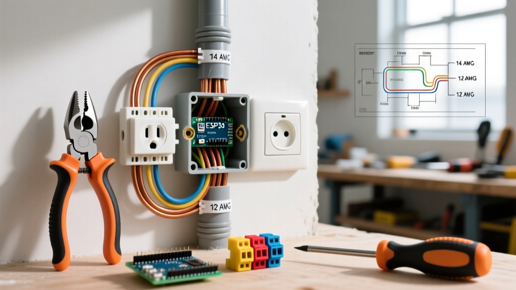
- Connectors: Wago 221 Lever-Nuts (~$0.45 each). In 2026, professional electricians heavily favor Wago lever-nuts over traditional twist-on wire nuts for joining neutrals and pigtails. They provide a visual confirmation window, require no twisting torque, and accommodate mixed 14 AWG and 12 AWG solid/stranded wires safely.
- The Switch: Leviton 15-Amp Decora Single Pole (Model R62-05613-02W, ~$3.50). Always choose switches with side-clamp terminal plates rather than open hook screws for easier installation.
Step-by-Step: Electrical Wiring Light Switch Installation
Step 1: Kill the Power and Verify
Locate your main service panel and switch off the corresponding 15A or 20A breaker. Never trust the wall switch to isolate power. Insert the Fluke 1AC-II into the box and touch it to all wires. If the tip glows red or beeps, the wrong breaker was tripped, or you have a multi-wire branch circuit (MWBC) sharing a neutral. The National Fire Protection Association (NFPA) mandates strict lockout/tagout procedures for professionals; as a homeowner, you must at least leave a physical note on the panel to prevent someone from turning it back on while you work.
Step 2: Extract and Inspect
Remove the faceplate and unscrew the existing switch. Gently pull it out of the box. Inspect the wire insulation. If the thermoplastic is brittle, cracked, or shows heat discoloration (browning), the circuit has likely been overloaded or subjected to high-resistance arcing. If the copper wire itself is heavily oxidized (dark brown/black), strip it back to bright, shiny copper using your Klein 11055 strippers.
Step 3: Precision Wire Preparation
Strip exactly 3/4 inch of insulation from the hot and switched-hot wires. If you are forming a J-hook for screw termination, bend the wire clockwise. Why clockwise? Because the terminal screw tightens clockwise. A counter-clockwise hook will be pushed out from under the screw head as you tighten it, resulting in a loose connection that will eventually arc and melt.
Step 4: Termination (Side Wiring vs. Backstabbing)
Expert Warning: The Danger of Backstabbing
Never use the push-in 'backstab' holes on the rear of the switch. These rely on a tiny internal brass spring clip to grip the wire. Over years of thermal expansion and contraction from the current load, the clip loosens. This creates a micro-gap, leading to series arcing, extreme heat, and potentially a junction box fire. Always use the side terminal screws or the internal clamp plates found on higher-end commercial switches.
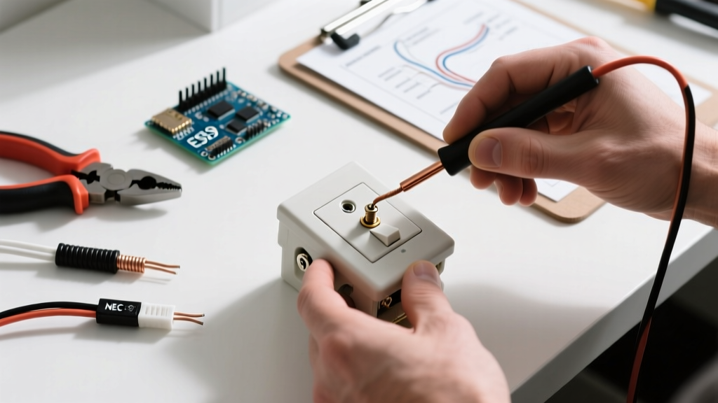
Loop your J-hook around the brass terminal screw. Ensure no bare copper is exposed outside the terminal plate (which risks shorting to the ground wire or metal box), and ensure no insulation is trapped under the plate (which causes an open circuit). Tighten the screw firmly until the clamp plate seats flush and the wire cannot be pulled free with a gentle tug.
Step 5: Grounding and Box Tucking
Connect the bare copper ground wire to the green grounding screw on the switch. If you are working in a metal junction box, the box itself must also be bonded to the ground path via a grounding pigtail. Once terminated, fold the wires in an accordion or 'Z' pattern. Push the switch into the box, ensuring no wires are pinched between the switch yoke and the drywall or box edge, which could degrade the insulation over time.
Modern Considerations: Smart Switches and the Neutral Wire
If you are upgrading to a smart switch (like the Lutron Caseta or Kasa Smart line), the electrical wiring light switch process changes slightly. Smart switches contain internal microcontrollers and Wi-Fi/Zigbee radios that require constant standby power. Therefore, they require a connection to the neutral wire to complete their internal low-power circuit. Before purchasing a smart switch, open your existing box and verify a bundle of white neutral wires is present in the back. If you only see a single white wire used as a 'switch leg' (often wrapped in black tape to denote it is actually a hot wire), you will need to buy a specific 'no-neutral required' smart switch, which typically utilizes a bypass capacitor installed up at the light fixture to prevent LED flickering.
Troubleshooting Failure Modes
Even with careful installation, issues can arise. Here is how to diagnose the three most common beginner mistakes:
- The Breaker Trips Instantly: You have created a dead short. This usually happens if a stray strand of bare copper from the hot wire is touching the grounded metal box or the ground wire. Turn off the breaker, pull the switch back out, and trim any 'whiskers' of copper.
- The Light Works, But the Switch Feels Warm: A warm switch indicates high resistance. This is almost always caused by a loose terminal screw, a backstabbed connection, or a wire that was nicked during stripping, reducing its cross-sectional area and causing it to act as a heating element under load.
- The Light Flickers When the Switch is Off: If you installed an LED bulb and a smart switch or dimmer without a neutral, the tiny trickle of leakage current passing through the LED driver is charging its internal capacitor until it flashes. Install an Lutron LUT-MLC bypass capacitor across the fixture's hot and neutral to resolve this.
Final Inspection
Before securing the faceplate, turn the breaker back on and operate the switch. Listen closely for any faint hissing or buzzing, which indicates a loose termination arcing. If silent, attach the faceplate using the provided 6-32 screws, being careful not to overtighten and crack the plastic. By adhering to these precise electrical wiring light switch protocols, you ensure a safe, code-compliant, and long-lasting installation that protects both your home and its occupants.