
Upgrading to a Double-Gang Configuration
Splitting a single overhead light circuit into two independent zones—such as controlling recessed can lights and a central pendant fixture separately—requires transitioning from a single-gang to a double-gang switch box. Understanding the correct wiring diagram for two light switches is critical to ensure independent operation, prevent shared-neutral tripping on AFCI breakers, and maintain compliance with the 2026 National Electrical Code (NEC). This guide walks you through the exact topology, box fill mathematics, and physical installation of two single-pole 15A switches in a shared 2-gang enclosure.
⚠️ CRITICAL SAFETY WARNING: Never rely solely on a wall switch to kill power. Always shut off the circuit at the main breaker panel and verify the absence of voltage using a non-contact voltage tester (NCVT) and a multimeter. The U.S. Consumer Product Safety Commission (CPSC) reports that electrical wiring errors are a leading cause of residential fires. If you are unsure about line vs. load identification, consult a licensed electrician.Tools, Materials, and 2026 Cost Breakdown
Before cutting drywall, gather professional-grade materials. Avoid builder-grade push-in back-stab switches; they are prone to thermal expansion failures and arcing over time.
- Enclosure: Carlon B225R 2-Gang Old-Work Non-Metallic Box (~$3.50)
- Switches: 2x Leviton 5225-W 15A Decora Single-Pole Switches (~$2.20 each)
- Cable: Southwire 14/2 NM-B Romex (for 15A circuits) or 12/2 NM-B (for 20A circuits) (~$0.65/ft)
- Connectors: Ideal 33 Yellow Wire Nuts (for 3-4 wires) & Ideal 34 Tan (for 2 wires) (~$8.00/box)
- Tools: Klein Tools 11-in-1 Multi-Tool, Fluke 1AC-II VoltAlert, Milwaukee Drywall Rotozip
The NEC Box Fill Calculation (Article 314.16)
One of the most common code violations in multi-switch installations is box overcrowding. The National Fire Protection Association (NFPA) mandates strict volume calculations to prevent wire insulation damage and heat buildup. For 14 AWG wire, each conductor counts as 2.0 cubic inches. For 12 AWG, it is 2.25 cubic inches.
| Item Description | Count (14 AWG) | Volume Allowance | Total Cubic Inches |
|---|---|---|---|
| Hot (Line) Conductor | 1 | 2.0 cu in | 2.0 |
| Switched Loads (to fixtures) | 2 | 2.0 cu in | 4.0 |
| Neutrals (passing through) | 3 | 2.0 cu in | 6.0 |
| Grounds (all count as 1) | 1 | 2.0 cu in | 2.0 |
| Device Yokes (2 switches x 2) | 4 | 2.0 cu in | 8.0 |
| Internal Cable Clamps (if any) | 1 | 2.0 cu in | 2.0 |
| Minimum Required Box Volume | 24.0 cu in | ||
Note: The Carlon B225R 2-gang old-work box provides 34.0 cubic inches of volume, making it fully compliant for this 14 AWG setup with ample room for wire folding.
Understanding the Wiring Diagram for Two Light Switches
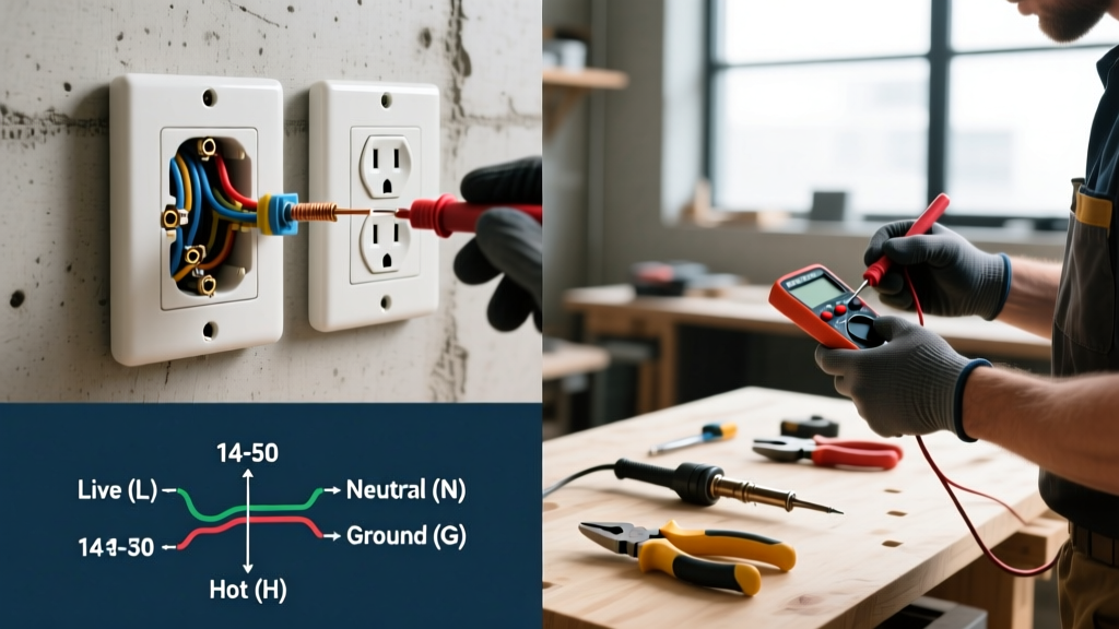
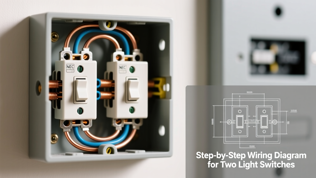
The topology for two independent single-pole switches sharing one power source relies on pigtailing. You cannot daisy-chain the hot wire through the brass screws of the first switch to the second switch if you want independent, reliable operation. Instead, the incoming Line (Hot) wire is spliced with two short jumper wires (pigtails) using a wire nut. Each pigtail feeds the brass terminal on its respective switch.
Line vs. Load Identification
Before disconnecting the old switch, identify the Line (power from the breaker) and the Load (power going to the light fixture). If you are working with existing cables, use a non-contact voltage tester. The Fluke electrical testing guide emphasizes testing a known live source before and after checking your target wire to ensure the NCVT battery and sensor are functioning correctly.
Step-by-Step Installation Guide
- Kill Power and Verify: Turn off the 15A or 20A breaker. Test the existing switch wires with your Fluke 1AC-II. Confirm zero voltage.
- Rough-In the 2-Gang Box: Remove the old single-gang box. Trace the Carlon B225R template on the drywall. Cut the opening using a Rotozip. Feed the incoming Line cable and the two Load cables into the new box. Secure the box to the drywall using the integrated flip-clamps.
- Strip Sheathing and Insulation: NEC 300.15 requires the non-metallic sheathing to enter the box by at least 1/4 inch. Strip exactly 3/4 inch of insulation from the copper conductors using the Klein 11-in-1 tool. Do not nick the copper, which creates a resistive hot-spot.
- Splice the Neutrals and Grounds: Group all white neutral wires together. Add a 6-inch 14 AWG white pigtail if you are installing smart switches later, but for standard toggle/Decora switches, simply twist the bare ends together, cap with an Ideal 33 Yellow wire nut, and push them to the back of the box. Repeat for the bare copper grounds, attaching a 6-inch green/bare pigtail that will eventually connect to the green ground screws on both switches and the metal box (if applicable).
- Execute the Hot Pigtail Splice: Take the incoming black Line wire and two 6-inch black 14 AWG pigtails. Strip 3/4 inch, twist them together tightly, and cap with an Ideal 33 Yellow wire nut. Give each wire a firm tug to ensure mechanical integrity.
- Terminate the Switches: Connect one black pigtail to the brass (Line) screw of Switch 1, and the other to Switch 2. Connect the black Load wire for Light 1 to the black (Load) screw of Switch 1, and the Load wire for Light 2 to Switch 2. Connect the ground pigtails to the green ground screws. Pro-Tip: Use the screw-actuated back-wire clamps on the Leviton 5225-W rather than wrapping the wire around the screw terminal. Back-wire clamps provide superior contact pressure and prevent loose connections over years of thermal cycling.
- Fold and Mount: Carefully accordion-fold the wires. Push the grounds and neutrals deep into the rear corners. Fold the hot and load wires behind the switch yokes. Drive the 6-32 mounting screws into the box ears, using a level to ensure the Decora straps are perfectly plumb before tightening fully.
Common Failure Modes and Troubleshooting
Even with a perfect wiring diagram for two light switches, physical installation errors can cause immediate failures.
- Breaker Trips Instantly: This almost always indicates a ground fault. A bare copper ground wire is likely touching one of the brass or black terminal screws on the side of the switch. Ensure all terminal screws are tightened down and wrap the sides of the switches with 3M Super 33+ electrical tape for an extra layer of dielectric insulation.
- AFCI Breaker Nuisance Tripping: If your panel uses Arc Fault Circuit Interrupters, ensure that the neutral wires for the two separate loads are not mixed or shared. Each light fixture's neutral must return on the exact same cable as its corresponding hot wire to prevent the AFCI from detecting an imbalance.
- Ghost Voltage on NCVT: When running two load cables parallel in the same box, capacitive coupling can induce a 'ghost' voltage reading on a disconnected load wire. Use a solenoid voltage tester (Wiggie) or a digital multimeter with a low-impedance (LoZ) setting to confirm true dead circuits.
Expert Insight: When upgrading to smart switches (like the Lutron Caseta PD-5S-DV) in a 2-gang box, heat dissipation becomes a major factor. Smart switches generate internal heat. If you are installing two smart dimmers side-by-side, you must break off the metal heat-sink fins on the inner edges of the switch yokes to fit them in the 2-gang Decora wallplate. However, doing this reduces the maximum wattage rating of the dimmer by roughly 25%. Always derate your LED load calculations accordingly.
Frequently Asked Questions
Can I use 12 AWG wire on a 15A Leviton switch?
Yes. The Leviton 5225-W is rated for both 14 AWG and 12 AWG copper conductors. However, 12 AWG wire is significantly stiffer, making box folding in a 2-gang enclosure much more difficult. If your breaker is 15A, using 14 AWG NM-B is perfectly legal and physically easier to work with.
Do I need to pigtail the ground wires if I am using a plastic box?
Yes. Even though a non-metallic (PVC) box does not require grounding itself, the NEC requires all equipment grounding conductors to be spliced together and connected to the green grounding terminals on the switches. This ensures a continuous fault-current path back to the panel.