
Decoding the Anatomy of a Duplex Switch
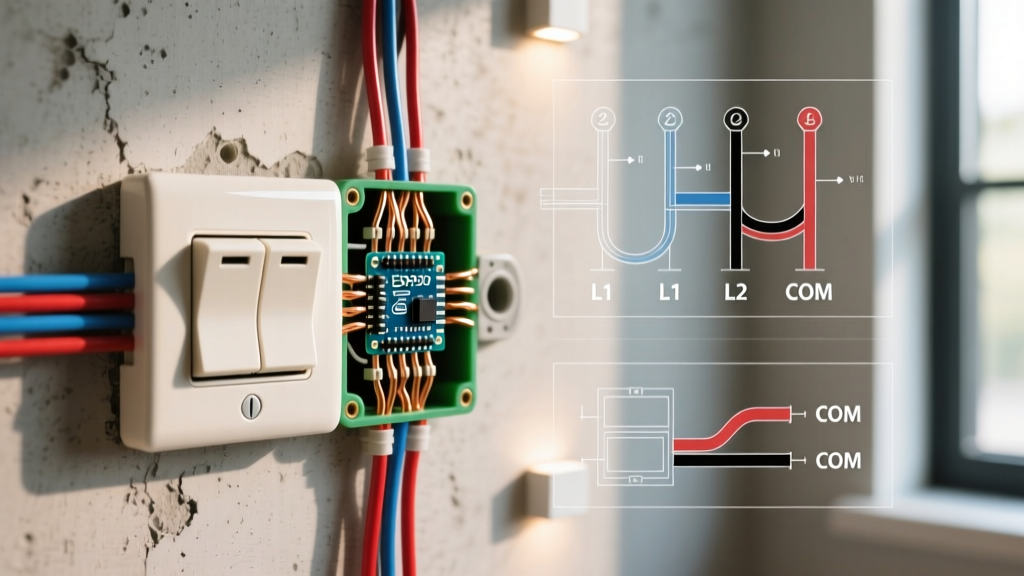
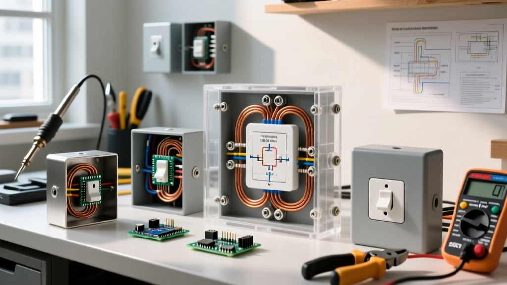
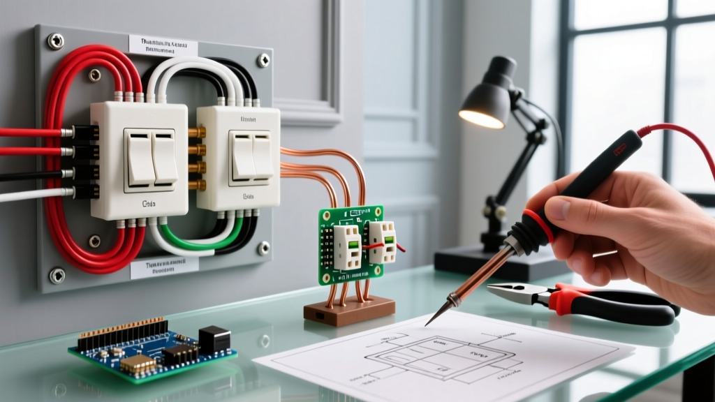
Understanding the wiring diagram for double light switch configurations is a fundamental skill for any DIY electrician or homeowner looking to control two separate fixtures from a single-gang wall box. Often referred to in the industry as a 'duplex switch' or 'twin switch' (such as the widely used Leviton 5622-2W or Eaton 1877), this device essentially houses two independent single-pole switches stacked vertically within one standard Decora or toggle strap.
Before pulling any wires, it is critical to understand that a duplex switch does not inherently split a single hot wire into two loads without proper pigtailing, nor does it automatically handle multi-wire branch circuits (MWBC) without specific breaker configurations. Misinterpreting the wiring diagram for double light switch installations is the leading cause of tripped AFCI breakers and melted terminal screws in residential retrofits.
Terminal Identification & Wire Color Mapping
Unlike a standard 3-way switch with its complex traveler system, a standard double switch relies on a straightforward line-and-load topology. Below is the standard terminal mapping you will encounter when reviewing manufacturer schematics.
| Terminal Type | Screw Color | Wire Color | Function & Code Notes |
|---|---|---|---|
| Common / Line In | Black or Dark Brass | Black or Red (Hot) | Incoming power from the breaker panel. Must be pigtailed if feeding both top and bottom switches. |
| Load 1 (Top) | Brass | Black or Red | Outgoing switched hot to Fixture A (e.g., bathroom vanity). |
| Load 2 (Bottom) | Brass | Black or Red | Outgoing switched hot to Fixture B (e.g., exhaust fan). |
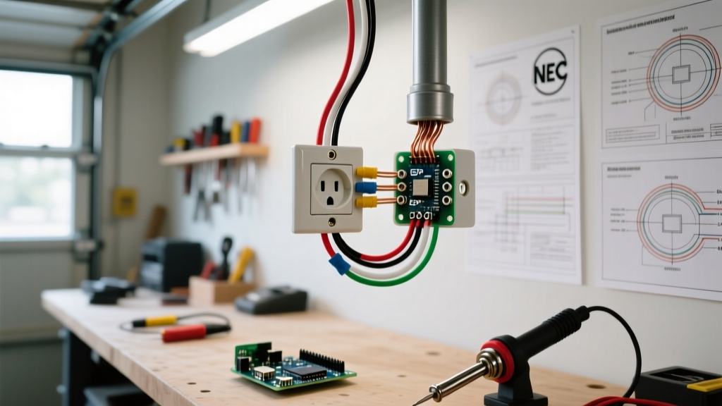
| Ground | Green | Bare Copper or Green | Safety ground. Must be bonded to the metal box if applicable per NEC 250.148. |
| Neutral (Smart Only) | Silver or White | White | Return path. Standard mechanical duplex switches do not use a neutral, but smart dual-switches require it. |
Scenario A: Standard Single-Pole Dual Load (15A Circuit)
The most common scenario requiring a wiring diagram for double light switch setups is a bathroom or kitchen where a single 15-amp, 120-volt circuit feeds both a light fixture and an exhaust fan or garbage disposal. In this scenario, you have one incoming hot wire (Line) and two outgoing hot wires (Loads), plus a shared neutral bundle that remains untouched in the back of the box.
The Pigtailing Imperative
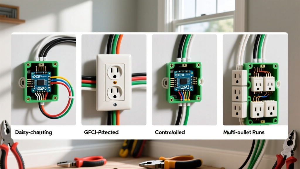
A critical mistake DIYers make is attempting to daisy-chain the hot wire through the first switch terminal to feed the second. According to the National Electrical Code (NEC), removing the device to service one switch must not interrupt the feed to the other if they are on the same yoke, but more importantly, terminal screws are generally only rated for a single wire termination. Therefore, you must create a pigtail.
- Strip the Wires: Use the 14 AWG gauge on your wire strippers to expose exactly 1/2 inch to 5/8 inch of copper on the incoming hot wire, the two load wires, and a 6-inch black pigtail wire.
- Join the Hots: Connect the incoming hot wire, Load 1, Load 2, and the pigtail using a WAGO 221-4 lever nut or a standard yellow wire nut. Note: WAGO connectors provide superior vibration resistance and eliminate the risk of loose twisted connections inside a crowded single-gang box.
- Terminate the Pigtail: Wrap the bare end of the pigtail clockwise around the dark brass 'Common' screw on the duplex switch and torque to the manufacturer's specification (usually 12-14 in-lbs).
- Connect the Loads: Attach the Load 1 wire to the top brass screw and Load 2 to the bottom brass screw.
Scenario B: The Multi-Wire Branch Circuit (MWBC) Edge Case
Here is where the standard wiring diagram for double light switch configurations fails, and where amateur electricians create severe fire hazards. If your switch box is fed by a Multi-Wire Branch Circuit (MWBC)—meaning you have two incoming hot wires (usually one black, one red) sharing a single white neutral wire—the two hot wires are on opposite phases (Leg A and Leg B) of a 240V split-phase system.
WARNING: You cannot pigtail the black and red incoming hot wires together on an MWBC. Doing so will create a direct 240-volt dead short, resulting in an immediate and violent arc flash at the breaker panel.
How to Wire a Duplex Switch on an MWBC
If you are replacing a single switch with a duplex switch on an MWBC, or wiring a new duplex switch to control two separate 20A appliances (like a dishwasher and disposal), the physical switch must be specifically rated for MWBC use, or you must use a different physical configuration.
- The Handle-Tie Method: The safest and most code-compliant method (NEC 210.4) is to abandon the single duplex switch and instead install two separate single-pole switches in a 2-gang box, utilizing a breaker handle-tie on the double-pole 20A breaker to ensure simultaneous disconnect.
- MWBC-Rated Duplex Switches: Some commercial-grade duplex switches feature an isolated internal bus bar or physical separation between the top and bottom line terminals, allowing you to land Leg A on the top switch and Leg B on the bottom switch. Always verify the manufacturer's specification sheet to ensure the device is explicitly rated for 2-pole/MWBC applications before proceeding.
Upgrading to Smart Dual Switches
As home automation matures in 2026, many homeowners are upgrading mechanical duplex switches to smart alternatives, such as the Enbrighten Z-Wave Plus Dual Rocker or Leviton Decora Smart dual-relay modules. The wiring diagram for double light switch smart upgrades introduces a new variable: the neutral wire.
Mechanical switches simply break the hot leg; they do not consume power. Smart switches contain internal Wi-Fi, Zigbee, or Z-Wave radios that require continuous 120V power. This means you must connect the switch's white neutral lead to the bundle of neutral wires in the back of the box. If your home was built before the 1980s, your switch boxes may lack a neutral wire. In these 'no-neutral' edge cases, you cannot use a standard dual smart switch. Instead, you must look into specialized systems like Lutron Caseta, which utilize a Pico remote mounted on the wall plate rather than a hardwired dual smart switch, bypassing the neutral requirement entirely.
Common Wiring Mistakes & Troubleshooting
Even with a correct wiring diagram for double light switch setups in hand, physical execution errors can lead to intermittent failures or code violations.
1. The Backstabbing Trap
Many modern duplex switches feature 'push-in' or backstab terminals on the rear. While the NEC allows these for 14 AWG solid copper wire on 15-amp circuits, they are strictly prohibited for 12 AWG wire. Furthermore, backstab connections rely on a tiny internal spring clip that can weaken over time due to thermal expansion and contraction, leading to arcing. Always use the side-screw terminals or the screw-to-clamp plate terminals for a permanent, high-surface-area connection.
2. Shared Neutrals and AFCI Trips
If you are wiring a double switch where the two loads share a neutral wire (a true MWBC), and your panel has been upgraded to modern Combination Type AFCI breakers, you may experience immediate nuisance tripping. AFCI breakers monitor the balance between the hot and neutral current. If the loads from Leg A and Leg B return on a shared neutral, the AFCI microprocessor may interpret the overlapping sine waves as a parallel arc fault. The solution is to ensure each leg of the MWBC has its own dedicated neutral wire run back to the panel, or to use a 2-pole AFCI breaker specifically designed to handle shared-neutral MWBC topologies.
3. Grounding to the Plastic Box
In older homes with metal junction boxes, the ground wire must be bonded to the box itself using a green grounding clip or a 10-32 ground screw tapped into the back of the box, in addition to running a pigtail to the green screw on the duplex switch. Simply attaching the ground to the switch strap is a violation if the box remains ungrounded.
Frequently Asked Questions
Can I use a 20-amp duplex switch on a 15-amp circuit?
Yes. A 20-amp rated switch (which features a T-slot neutral/ground face if it were a receptacle, but internally uses heavier brass contacts for switches) is perfectly safe and legal to use on a 15-amp circuit with 14 AWG wire. The reverse, however, is a severe code violation: you cannot use a 15-amp switch on a 20-amp circuit.
Why does my double switch have a break-off fin?
Some duplex switches feature a small metal fin connecting the two brass load screws, or the two dark brass line screws. This fin is designed to be snapped off with needle-nose pliers if you are feeding the top and bottom switches from two completely different circuits (such as in an MWBC scenario). If you are pigtailing a single incoming hot wire to feed both switches, the fin must remain intact to distribute power internally.
What is the maximum box fill for a double switch setup?
A single-gang box housing a duplex switch, two 14/2 cables (one line, one load), and one 14/3 cable (second load) can quickly exceed standard box fill limits. According to NEC Article 314, a standard 18-cubic-inch single-gang 'old work' box is usually sufficient, but if you are adding smart switches with bulky wire nuts and neutral pigtails, you should upgrade to a 22-cubic-inch deep single-gang box to prevent pinching wires against the drywall.