
Why the Correct Screw Size for Electrical Outlet Hardware Matters
When installing a standard 15-amp or 20-amp duplex receptacle, selecting the correct hardware is just as critical as stripping the wires to the right length. Using the wrong screw size for electrical outlet mounting or grounding can lead to stripped box threads, loose yoke connections, galvanic corrosion, and severe fire hazards. In 2026, with the rise of high-draw USB-C receptacles and smart outlets that generate more ambient heat, ensuring a rock-solid mechanical and electrical bond is non-negotiable.
Many DIYers mistakenly reach for drywall screws or wood screws from their general hardware bin. This is a direct violation of the National Electrical Code (NEC) and compromises the UL listing of the device. According to the National Fire Protection Association (NFPA), electrical hardware must be specifically rated for the mechanical shear strength and environmental conditions of an electrical enclosure.
Expert Insight: The terminal screws on the receptacle itself (the brass, silver, and green screws that hold the wires) are pre-installed by the manufacturer and rated to specific torque limits. Your responsibility during installation is sourcing the correct mounting and grounding screws to secure the device to the electrical box.
Master Hardware Reference Chart
Before beginning your step-by-step installation, verify that your hardware kit contains the following standard sizes. A contractor pack of 100 #6-32 mounting screws typically costs between $7 and $10 in 2026, while a 50-pack of #10-32 green grounding screws runs about $8.
| Application | Screw Size | Thread Pitch | Standard Length | Head Type / Drive |
|---|---|---|---|---|
| Receptacle Mounting (Yoke to Box) | #6-32 UNC | 32 TPI | 3/4" (Standard) to 1.5" (Deep) | Pan Head / Phillips or Quadrex |
| Metal Box Grounding Pigtail | #10-32 UNC | 32 TPI | 1/2" to 3/4" | Hex Head (Green) / 5/16" Nut Driver |
| Oversize Mounting (Stripped Holes) | #8-32 UNC | 32 TPI | 3/4" to 1" | Pan Head / Phillips #2 |
| Terminal Wire Connection | #10-32 (Internal) | 32 TPI | N/A (Captive) | Slotted / Torque Screwdriver Required |
Step-by-Step Installation: Mounting and Grounding
Follow this precise workflow to ensure your outlet is mechanically secure, properly grounded, and fully compliant with modern electrical standards.
Step 1: Inspect and Prep the Electrical Box Threads
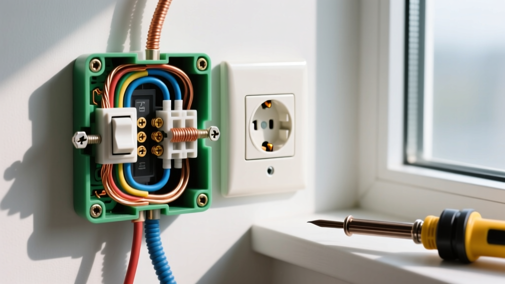
Whether you are working with a metal mud ring, a nail-on plastic box, or an old-work retrofit box, the mounting ears feature pre-tapped holes designed specifically for #6-32 UNC screws.
- Metal Boxes: Inspect the threaded holes for drywall mud, paint, or rust. Use a #6-32 bottoming tap to clean out the threads. Forcing a screw through dried joint compound will strip the soft metal of the mud ring.
- Plastic Boxes: Modern polycarbonate boxes (like those from Carlon or Arlington) feature molded brass inserts. Never use self-tapping sheet metal screws here; they will crack the brass insert and ruin the box's UL fire rating.
Step 2: Secure the Grounding Pigtail (Metal Boxes Only)
If you are installing into a metal electrical box, NEC 250.148 requires a dedicated grounding connection to the box itself. Plastic boxes do not require this step.
- Strip 3/4" of insulation from a 12 AWG or 14 AWG bare copper grounding wire (matching your circuit gauge).
- Locate the pre-tapped grounding hole in the back or side of the metal box.
- Insert a #10-32 green hex-head grounding screw. The 10-32 size provides the necessary thread engagement and surface area to safely clear fault currents.
- Drive the screw using a 5/16" nut driver or hex bit until the wire is pinned tightly against the bare metal. Do not over-torque, as you can snap the screw head off inside the box.
Step 3: Terminate the Wires and Align the Yoke
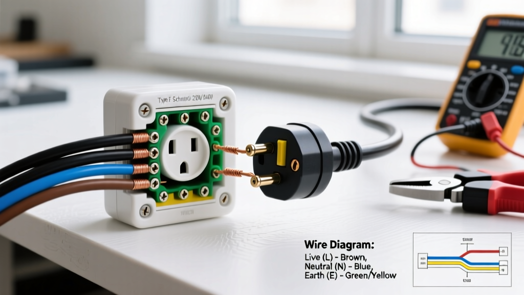
Before mounting, connect your hot, neutral, and ground wires to the receptacle's captive terminal screws. According to Leviton Technical Support, side-wiring terminal screws should be torqued to approximately 14 in-lbs to prevent arcing and thermal creep over time. Use a calibrated torque screwdriver to meet NEC 110.14(D) requirements.
Carefully fold the wires into the box using a clockwise loop pattern. Align the receptacle yoke (the metal mounting strap) over the plaster ring or box ears.
Step 4: Drive the #6-32 Mounting Screws
This is where the correct screw size for electrical outlet mounting proves its worth.
- Insert the #6-32 x 3/4" pan head screws through the elongated slots on the receptacle yoke.
- Thread them into the box by hand or with a low-torque setting on your drill to prevent cross-threading.
- Tighten evenly, alternating between the top and bottom screws to keep the yoke centered. The elongated slots allow for minor leveling adjustments before final tightening.
Critical Edge Cases and Troubleshooting
Real-world installations rarely go exactly by the book. Here is how to handle common hardware failures and structural anomalies.
The Stripped 6-32 Hole (The 8-32 Oversize Fix)
If you are replacing an outlet in an older home and the #6-32 mounting hole in the metal box is stripped out, do not use a longer screw or wrap the threads in electrical tape. Instead, use a #8-32 tap to cut new, slightly larger threads into the existing hole. Once tapped, you can securely mount the receptacle using an #8-32 x 3/4" screw. This restores full mechanical shear strength and passes inspection.
Deep-Set Boxes and Tile Backsplashes
When an electrical box is set too far back into the wall (more than 1/4" from the finished surface per NEC 314.20), you must use a plaster ring extender (such as the Arlington BE1). Standard 3/4" screws will not reach the box threads through the extender. You must upgrade to #6-32 x 1.5" or 2" screws to ensure at least 1/2" of thread engagement inside the metal box ear.
Common Code Violations to Avoid
According to OSHA Electrical Safety Guidelines and local inspectors, the following hardware mistakes are immediate red flags:
- Using Drywall Screws: Drywall screws are brittle, prone to snapping under shear stress, and lack the corrosion resistance required for electrical enclosures. Their bugle heads also sit improperly in the yoke's countersink.
- Using Wood Screws: Wood screws have a tapered shank and a coarse thread pitch that will instantly destroy the delicate 32-TPI threads tapped into a metal electrical box.
- Missing Ground Screws: Failing to bond a metal box to the grounding system with a #10-32 green screw leaves the enclosure energized during a fault condition, creating a lethal shock hazard.
Frequently Asked Questions
Can I use stainless steel screws for outdoor outlet mounting?
Yes, but with a caveat. While stainless steel resists corrosion in damp locations, it is susceptible to galvanic corrosion when in direct contact with galvanized steel boxes. If installing an outdoor receptacle in a wet location, use hot-dipped galvanized #6-32 screws or apply a dielectric anti-seize compound to stainless screws to prevent the metals from fusing together over time.
What size screw holds the plastic faceplate on?
Standard nylon or polycarbonate faceplates (like the Leviton Decora or standard duplex covers) use #6-32 x 5/16" flat head machine screws. These are almost always included with the faceplate. Do not use your mounting screws for the faceplate, as the 3/4" length will bottom out inside the receptacle's threaded yoke hole, potentially cracking the plastic cover.
Do smart outlets require different mounting hardware?
Smart outlets (Wi-Fi or Zigbee enabled) are significantly deeper and heavier than standard duplex receptacles. While they still use the standard #6-32 mounting screws, the added weight and depth often require you to use the top and bottom mounting holes on the electrical box rather than the standard center ears to prevent the device from sagging over time.