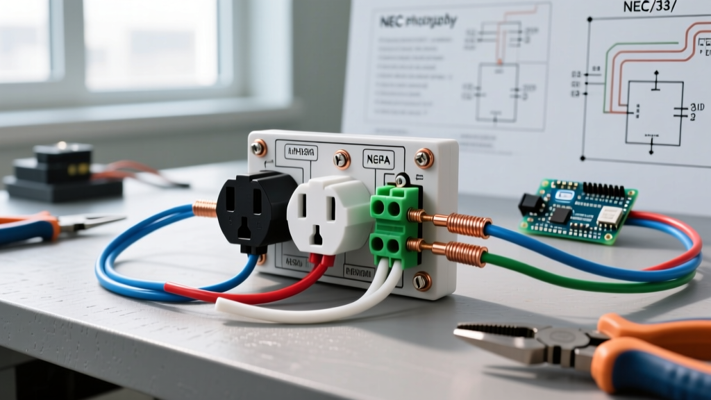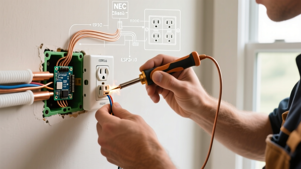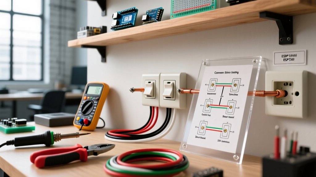

The Anatomy of a 3-Way Circuit
Unlike a standard single-pole switch that simply opens or closes a single circuit path, a 3-way switch is electrically classified as a Single-Pole Double-Throw (SPDT) device. It features three terminal screws (excluding the green grounding screw): one Common terminal (usually a darker, black or dark-brass screw) and two Traveler terminals (lighter brass screws). Understanding this internal mechanism is the foundational prerequisite for mastering 3 way electrical switch wiring in any residential or commercial environment.
Before stripping any wire insulation, always verify the circuit is de-energized using a reliable non-contact voltage tester, such as the Klein Tools NCVT-3, and confirm with a digital multimeter like the Fluke 117. According to OSHA electrical safety guidelines, lockout/tagout procedures or verified dead-front testing are mandatory to prevent arc flash and electrocution hazards.
Scenario 1: Power Source at the First Switch (Standard Hallway)
This is the most straightforward and common configuration found in modern residential construction. The main power feed from the breaker panel enters the first switch box, and the load wire continues from the second switch to the light fixture.
Step-by-Step Execution
- At Switch 1 (Line Side): The incoming 14/2 NM-B (or 12/2 for 20A circuits) black hot wire connects directly to the Common terminal. The incoming white neutral wire is spliced with a wire nut to the white neutral wire of the 14/3 cable running to Switch 2.
- The Traveler Run: The black and red wires of the 14/3 NM-B cable connect to the two brass Traveler terminals on Switch 1. The white wire of this 14/3 cable acts as the neutral pass-through.
- At Switch 2 (Load Side): The black and red traveler wires from the 14/3 cable connect to the brass Traveler terminals. The white neutral wire splices directly to the 14/2 NM-B neutral running up to the light fixture.
- The Load Connection: The black wire of the 14/2 cable heading to the light fixture connects to the Common terminal on Switch 2. This wire becomes the 'switched hot' that powers the luminaire only when both switch internals align the circuit path.
Scenario 2: Power at the Light Fixture (The 'Dead-End' Stairwell)
Often encountered in older homes or complex stairwells, this scenario occurs when the main power feed enters the ceiling junction box (the light fixture location) first. Switch 2 becomes a 'dead-end' 3-way, meaning it only receives a single 14/3 cable from Switch 1, with no direct line or load connections.
Wiring the Dead-End Configuration
- At the Light Fixture Box: The incoming hot (black) from the panel is spliced to the white wire of the 14/3 cable heading down to Switch 1. Critical NEC Rule: You must re-identify this white wire with black electrical tape or heat shrink at both ends to indicate it is being used as an ungrounded (hot) conductor.
- At Switch 1: The re-identified white wire (now carrying line voltage) connects to the Common terminal. The black and red wires connect to the Traveler terminals.
- At Switch 2 (Dead-End): The black and red wires from the second 14/3 cable connect to the Traveler terminals. The white wire of this second 14/3 cable is also re-identified and connects to the Common terminal. This white wire carries the 'switched hot' back up to Switch 1.
- Back at Switch 1: The re-identified white wire returning from Switch 2 is spliced to the black wire of the first 14/3 cable, which carries the final switched hot back up to the light fixture's black load wire.
Pro Tip: Dead-end 3-ways are notorious for confusing DIYers during replacements. Always use a multimeter to identify the constant hot wire versus the switched return wire before disconnecting the old switch.
Scenario 3: Upgrading to Smart 3-Way Switches
Integrating smart home technology into a 3-way circuit introduces new variables, primarily the requirement for a neutral wire at the switch box to power the internal Wi-Fi/Zigbee radios.
Product Comparison: Lutron Caséta vs. Kasa Smart
- Lutron Caséta (Model PD-5S-DV): Priced around $65 for the switch and Pico remote kit. This system bypasses the traditional mechanical 3-way wiring entirely. You wire the PD-5S-DV at the main line/load box (requiring line, load, and neutral) and cap off the travelers. The second location is converted to a wireless Pico remote mounted in a wallplate. This is the ultimate solution for 'dead-end' scenarios where pulling a neutral is impossible.
- Kasa Smart 3-Way (Model KS230): Priced around $25 per switch. This requires a physical neutral wire present in both switch boxes. It utilizes the existing traveler wires to send digital signals between the master and add-on switches. If your home lacks neutrals at the switch boxes (common in pre-2011 construction), this system will not function without a costly rewiring effort.
Wire Color Mapping & Terminal Matrix
Standardizing your wire color usage prevents catastrophic miswiring. Refer to this matrix when terminating your connections:
| Wire Color (NM-B) | Function in 3-Way Circuit | Terminal Connection |
|---|---|---|
| Black (14/2 or 12/2) | Constant Line Hot or Switched Load | Common Screw (Dark) |
| White (14/2 or 12/2) | Grounded Neutral Return | Wire Nut Splice (Not on switch) |
| Red (14/3 or 12/3) | Traveler 1 | Brass Screw 1 |
| Black (14/3 or 12/3) | Traveler 2 | Brass Screw 2 |
| White (14/3 or 12/3) | Neutral Pass-through OR Re-identified Hot | Splice OR Common Screw (if taped) |
| Bare Copper | Equipment Grounding Conductor | Green Screw & Metal Box Pigtail |
NEC 2026 Compliance & Box Fill Calculations
When executing 3 way electrical switch wiring, box fill violations are the most common code infringement cited by inspectors. Under NEC Article 314.16, every current-carrying conductor, clamp, and device yoke counts toward the cubic inch capacity of the electrical box.
For 14 AWG wire, each conductor counts as 2.0 cubic inches. For 12 AWG, it is 2.25 cubic inches. A standard 3-way switch box contains the device yoke (counts as 2 conductors), the ground wire (counts as 1), and the current-carrying wires. A standard single-gang 'old work' box offers roughly 14 to 18 cubic inches. However, a 3-way switch box housing a 14/2 and a 14/3 cable will easily require 22.5 cubic inches of space. Always opt for deep single-gang boxes (minimum 22.5 cu in) to accommodate the bulk of three traveler/line wires and wire nuts without damaging the insulation against the device yoke. For comprehensive code standards, always consult the latest National Electrical Code (NEC) published by the NFPA.
Troubleshooting Common 3-Way Failures
Even experienced electricians occasionally miswire a 3-way circuit. If the circuit fails to operate correctly, diagnose the issue using these specific failure modes:
- Symptom: Light only turns on/off from one switch location.
Diagnosis: The line or load hot wire was mistakenly connected to a brass Traveler terminal instead of the dark Common terminal on one of the switches. Alternatively, the travelers and the common wire were swapped at the light fixture box in a 'power-at-light' scenario. - Symptom: Light works, but the switches behave inversely (e.g., both must be 'down' to turn on).
Diagnosis: This is not a wiring fault, but a mechanical orientation issue. Simply remove the faceplate, unscrew the switch, and rotate it 180 degrees. - Symptom: Breaker trips immediately upon toggling.
Diagnosis: A dead short. This usually occurs when a re-identified white wire (acting as a hot) in a dead-end scenario accidentally touches the bare copper ground wire or the metal box due to poor wire nut taping or overcrowded box fill.
For further insights on optimizing residential lighting layouts and control efficiency, the U.S. Department of Energy's guide on lighting controls provides excellent baseline metrics for integrating mechanical switches with modern LED loads.