
Decoding the Wiring Diagram for Light Switch Safety
Every year, electrical malfunctions and improper wiring cause thousands of residential fires. When homeowners and novice DIYers search for a wiring diagram for light switch setups, they are often looking for a quick visual guide to connect black and white wires. However, from the perspective of a licensed electrician, a wiring diagram is not just a connection map; it is a strict blueprint for life safety and National Electrical Code (NEC) compliance. Ignoring the nuances of these diagrams leads to switched neutrals, overloaded junction boxes, and severe arc flash hazards.
According to the NFPA's Electrical Safety division, electrical distribution and lighting equipment are consistently among the top causes of home structure fires. This guide breaks down the anatomy of standard and 3-way switch diagrams through the lens of modern NEC code requirements, ensuring your installation is both functional and legally compliant.
The Anatomy of a Standard Single-Pole Wiring Diagram
A standard single-pole switch controls a light fixture from one location. The basic wiring diagram for light switch configurations of this type involves four critical conductors: Line (Hot), Load (Switched Hot), Neutral, and Ground.
- Line (Hot): The continuous power source from the breaker panel, typically a black wire, connected to the bottom brass terminal.
- Load (Switched Hot): The wire carrying power to the light fixture only when the switch is closed, typically connected to the top brass terminal.
- Neutral: The return path for the current (white wire). In a standard single-pole diagram, the neutrals from the line and load cables are spliced together and bypass the switch entirely.
- Ground: The bare copper or green insulated wire, bonded to the green grounding screw on the switch strap and the metal box (if applicable).
CRITICAL SAFETY WARNING: Never use the ground wire as a neutral return path. This 'bootleg neutral' violates NEC 250.142 and creates a lethal shock hazard on all grounded metal surfaces in the home.
The 'Neutral at the Switch' Rule (NEC 404.2(C))
One of the most vital updates in recent NEC cycles that impacts the wiring diagram for light switch installations is Section 404.2(C). This code mandates that a neutral conductor must be present at almost all switch boxes controlling lighting. Why? The proliferation of smart switches (like the Lutron Caseta or Leviton Decora Smart Wi-Fi models, which retail between $35 and $60) requires a continuous low-current return path to power their internal radios and LEDs. If your diagram lacks a neutral at the switch box, you are pre-wiring for obsolescence and potential code violations.
Box Fill Calculations: The Hidden Diagram Hazard
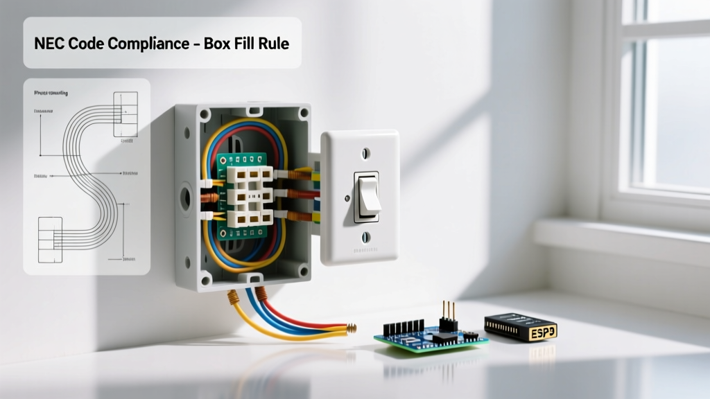
A wiring diagram for light switch setups rarely illustrates the physical limitations of the electrical box. Cramming too many wires into a standard plastic nail-on box causes heat buildup and insulation damage. NEC 314.16 dictates strict 'box fill' calculations based on cubic inch (cu in) volume.
Calculating Box Fill for a 15-Amp Circuit (14 AWG Wire)
For 14 AWG wire, each current-carrying conductor counts as 2.0 cubic inches. Let us run the math on a standard switch loop diagram:
- Line Cable (14/2 NM-B): 1 Black (Hot), 1 White (Neutral) = 2 wires.
- Load Cable (14/2 NM-B): 1 Black (Switched Hot), 1 White (Neutral) = 2 wires.
- Equipment Grounds: All bare/green wires count as a single 1 wire allowance.
- The Switch Device: The yoke/strap of the switch counts as 2 wires.
- Internal Clamps: Count as 1 wire (if present).
Total Allowance: 2 + 2 + 1 + 2 + 1 = 8 wire allowances.
8 allowances × 2.0 cu in = 16.0 cubic inches required.
A standard 18 cu in 'old work' or nail-on box is legally sufficient. However, if you add a second cable for a daisy-chained outlet, you will exceed 18 cu in and must upgrade to a 22 cu in deep box.
3-Way Switch Diagrams and Traveler Identification
Controlling a light from two locations requires a 3-way wiring diagram. This setup introduces 'traveler' wires that run between the two switches. A massive safety failure occurs when DIYers misuse wire colors in these diagrams.
| Conductor Function | Standard NEC Color Code | Re-Identification Requirement |
|---|---|---|
| Line / Hot | Black or Red | None |
| Neutral | White or Gray | Must not be used as hot/traveler |
| Traveler 1 | Red (in 14/3 or 12/3 NM-B) | None |
| Traveler 2 | Black (in 14/3 or 12/3 NM-B) | None |
| Switched Hot (White) | White | Must be painted/taped Black or Red per NEC 200.7(C)(2) |
If your 3-way wiring diagram utilizes a 14/2 cable between switches (a dangerous and outdated 'switch loop' method), the white wire is acting as a traveler or hot. NEC 200.7(C)(2) strictly requires you to permanently re-identify this white wire with black electrical tape or marker at both terminations. Failing to do so endangers future electricians who assume the white wire is a de-energized neutral.
Common Code Violations and Failure Modes
Even with a perfect wiring diagram for light switch execution, physical installation errors lead to catastrophic failures. Watch for these specific edge cases:
1. Backstabbing vs. Screw Terminals
Many budget switches (like the standard $1.50 Leviton 15A single-pole models) feature push-in 'backstab' connectors on the rear. While technically UL-listed, these spring-loaded connections are notorious for loosening over 5 to 10 years due to thermal expansion and contraction cycles. This loosening increases resistance, generating immense heat and leading to arc faults. Expert Directive: Always use the side screw terminals or the screw-to-clamp plates. Wrap the wire clockwise around the screw so tightening the screw pulls the loop closed.
2. Ignoring Torque Specifications (NEC 110.14(D))
Modern NEC code requires that terminations be tightened to the manufacturer's specified torque. Over-tightening strips the brass screw head or shears the wire; under-tightening causes arcing. For most standard 15A residential switches, the required torque is between 14 and 16 inch-pounds. Professionals use a calibrated tool like the CDI 401SM torque screwdriver to ensure exact compliance.
Step-by-Step Safe Installation Protocol
Before executing any wiring diagram for light switch configurations, you must adhere to strict lockout and verification procedures. The OSHA's Control of Hazardous Energy guidelines emphasize that assuming a circuit is dead is a fatal error.
- Lockout/Tagout (LOTO): Turn off the breaker and apply a physical lock or heavy tape over the panel slot to prevent accidental re-energization while you are working.
- Non-Contact Voltage Testing: Use a high-quality tester like the Klein Tools NCVT-3 to verify the absence of voltage at the switch box. Test a known live circuit first to verify the tool's battery is functional.
- Multi-Meter Verification: For absolute certainty, use a solenoid tester or digital multimeter (like the Fluke T6-1000) to test Line-to-Ground and Line-to-Neutral.
- Strip to Exact Length: Use the gauge hole on your wire strippers. For 14 AWG, strip exactly 3/4 inch of insulation. Exposed copper outside the terminal creates a short-circuit hazard; insulation under the terminal screw causes a loose, high-resistance connection.
- Secure the Yoke: Ensure the switch strap sits flush against the drywall. Use shims (like the Caddy TS1) if the box is set too deep, preventing the faceplate from cracking and exposing live voltage.
Frequently Asked Questions (FAQ)
Can I wire a light switch without a ground wire?
If you are working in an older home with legacy knob-and-tube or early ungrounded NM cable, the NEC allows for specific exceptions. You may replace a broken switch with a new one, but you must use a GFCI-protected switch or label the box 'No Equipment Ground'. However, if you are running new cable, a ground wire is absolutely mandatory per the National Fire Protection Association (NFPA 70).
Does it matter which brass screw the hot and load wires connect to?
On a standard single-pole switch, the brass screws are internally bridged. Electrically, it does not matter which brass screw receives the Line and which receives the Load. However, for uniformity and professional troubleshooting, electricians typically wire the Line (source) to the bottom terminal and the Load (fixture) to the top terminal.
Why does my smart switch require a neutral wire?
Smart switches contain internal microprocessors, Wi-Fi/Z-Wave radios, and LED status indicators. These components require a continuous 120V circuit to remain powered even when the light is turned 'off'. Without a neutral wire to complete this low-current control circuit, the switch will either fail to operate or attempt to leak current through the light bulb, causing LEDs to flicker or glow ghost-like in the dark.