
Mastering the Wiring Diagram for a 7 Way Plug: An Inspection & Testing Guide
The 7-way blade connector is the critical nervous system linking your tow vehicle to your RV or heavy-duty trailer. Governed by industry standards and referenced in the Recreation Vehicle Industry Association (RVIA) guidelines, this single junction handles everything from 12V auxiliary power and electric brakes to turn signals and reverse lights. Yet, it remains one of the most common points of failure on the road. Moisture ingress, pin splay, and undersized wiring can lead to catastrophic brake failure or melted sockets.
As an electrical inspector, relying on a basic visual check is insufficient. You need a systematic approach grounded in the correct wiring diagram for a 7 way plug. This comprehensive 2026 inspection and testing guide will walk you through advanced multimeter diagnostics, voltage drop calculations, and edge-case troubleshooting to ensure your rig is safe, compliant, and road-ready.
The Standard Wiring Diagram for a 7 Way Plug (Blade Style)
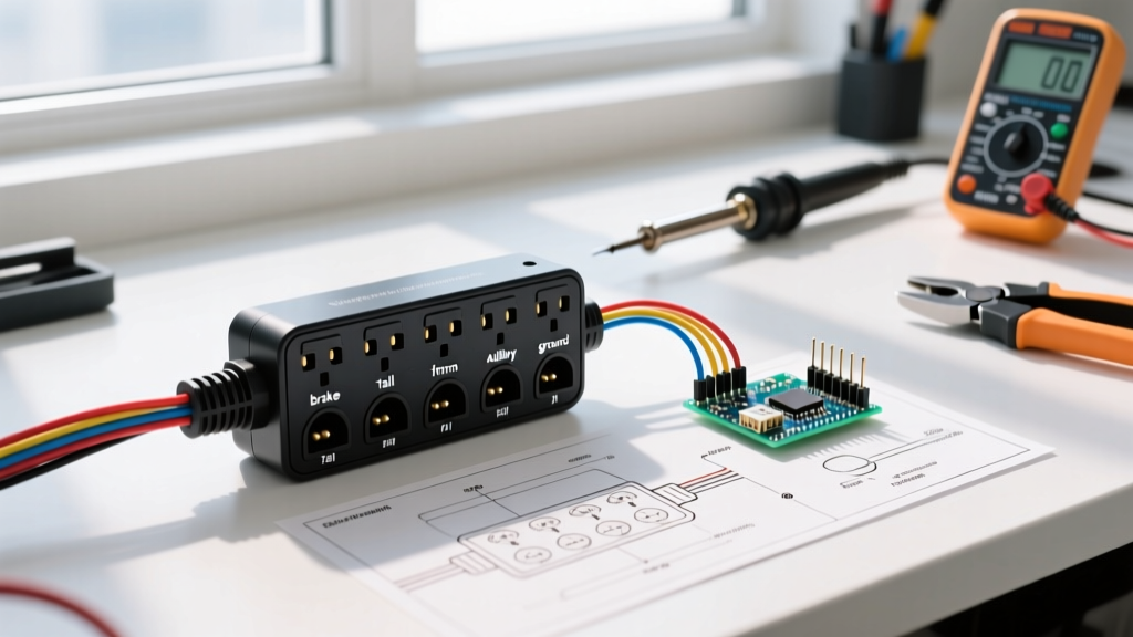
Before testing, you must understand the pinout. The standard RV 7-way blade connector follows a specific layout. The table below details the pin positions when looking directly at the face of the male trailer plug (the side with the exposed prongs).
| Pin Position (Clock Face) | Function | Standard Wire Color | Min. Recommended Gauge | Typical Load / Notes |
|---|---|---|---|---|
| Center | Ground (White) | White | 8 AWG | Must handle return current for all circuits. Undersizing causes erratic brakes. |
| 1 o'clock | Tail / Running Lights | Brown | 12 AWG | Clearance lights, license plate, and running lamps. |
| 3 o'clock | Right Turn / Stop | Green | 12 AWG | Combines turn signal and brake light for the right side. |
| 5 o'clock | Electric Brakes | Blue | 10 AWG | Carries up to 12V DC from the brake controller. High current draw. |
| 7 o'clock | 12V Auxiliary Power | Black or Red | 10 AWG (8 AWG preferred) | Charges RV house batteries, powers interior 12V systems. |
| 9 o'clock | Left Turn / Stop | Yellow | 12 AWG | Combines turn signal and brake light for the left side. |
| 11 o'clock | Reverse Lights / Aux | Purple | 14 AWG | Reverse lamps or auxiliary solenoid for surge brake lockout. |
Essential Diagnostic Tools for 2026
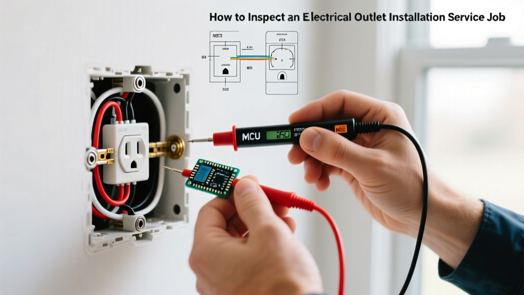
To properly execute this inspection protocol, you need more than a cheap test light. Modern RVs utilize complex CAN bus systems and sensitive LiFePO4 battery management systems (BMS) that require precise voltage readings.
- True RMS Multimeter: A Fluke 117 or Klein Tools MM400 is mandatory for accurate DC voltage and resistance readings.
- Circuit Tester: The Hopkins 40375 or similar 7-way blade tester provides quick visual confirmation of pin activation without needing a second person.
- Contact Cleaner & Protectant: CRC QD Contact Cleaner for removing oxidation, followed by Permatex 22058 Dielectric Tune-Up Grease to prevent moisture ingress.
- Heat Gun & Adhesive-Lined Heat Shrink: For repairing compromised wire jackets near the plug housing.
Step-by-Step Inspection & Testing Protocol
Phase 1: Visual and Mechanical Inspection
Before applying power, inspect the physical integrity of both the male plug and female receptacle.
- Check for Pin Splay: Look closely at the male prongs. If the blades are bent outward or appear loose, they will not maintain adequate tension against the female contacts. This high-resistance connection generates immense heat, leading to the infamous 'melted plug' phenomenon.
- Inspect for Heat Bluing: Discoloration or melting on the plastic housing around the Ground (Center) or 12V Aux (7 o'clock) pins indicates chronic overloading or poor contact tension.
- Wire Jacket Integrity: Bend the cable 90 degrees right where it enters the rubber plug housing. Cracking here exposes copper to road salt and moisture, inevitably causing a short.
Phase 2: Tow Vehicle Receptacle Voltage Testing
Plug your multimeter into the tow vehicle's female socket to verify the source power. Start the engine to ensure the alternator is supplying system voltage (typically 13.8V to 14.4V).
- Ground Verification: Set your multimeter to DC Volts. Place the black probe on a known good chassis ground on the truck, and the red probe on the Center Pin. It should read 0.00V. If it reads voltage, your truck's receptacle ground wire is broken or corroded.
- 12V Aux Pin (7 o'clock): Probe the 7 o'clock pin. You should see full alternator voltage (13.8V+). If it reads 12.0V or lower with the engine running, there is a voltage drop in the tow vehicle's wiring harness, often caused by a corroded factory relay or undersized wiring.
- Brake Pin (5 o'clock): Have an assistant press the brake pedal or manually slide the brake controller override. You should see voltage spike to 12V.
Phase 3: Trailer Side Continuity and Resistance
Disconnect the trailer. Set your multimeter to the Ohms (Ω) or Continuity setting.
- Ground Continuity: Place one probe on the Center Pin (White) and the other on the bare metal trailer frame. You should read near 0.00 Ω. If resistance is high, clean the frame grounding point and apply anti-corrosion compound.
- Electric Brake Resistance: Probe the 5 o'clock pin (Blue) and the Center pin (Ground). A standard electric brake assembly draws about 3.5 to 4.0 ohms. If you have a dual-axle trailer (4 brakes), the parallel resistance should read approximately 0.8 to 1.0 ohms. A reading of 'OL' (Open Loop) indicates a severed blue wire; a reading of 0.00 Ω indicates a dead short.
Advanced Troubleshooting: Edge Cases & Failure Modes
The LiFePO4 Charging Dilemma: 12V Aux Voltage Drop
In 2026, the majority of modern RVs have upgraded to Lithium Iron Phosphate (LiFePO4) house batteries. Unlike lead-acid batteries, which will accept a trickle charge at 12.6V, a LiFePO4 BMS requires a minimum of 13.8V to 14.2V to activate charging.
Many RVers use the wiring diagram for a 7 way plug to diagnose why their lithium batteries aren't charging while driving. The culprit is almost always voltage drop on the 12V Aux (Black/Red) wire. If the manufacturer used cheap 12 AWG wire for a 25-foot run from the truck to the RV battery, the resistance will drop the 14.2V alternator output down to 12.8V by the time it reaches the BMS. The BMS will reject the charge. Solution: Run a dedicated 6 AWG or 4 AWG marine-grade tinned copper wire directly from the tow vehicle's alternator post to the trailer battery, bypassing the 7-way plug's 12V pin entirely for charging purposes.
Electric Brake 'SH' (Short) Codes
If your brake controller displays an 'SH' code, the blue wire is shorting to ground. While a severed wire is possible, the most common edge case is moisture ingress inside the 7-way plug housing itself. Water bridges the gap between the 5 o'clock pin and the center ground pin. Disassemble the plug housing, blast it with CRC QD Contact Cleaner, dry it thoroughly, and pack the interior cavity with dielectric grease before reassembling.
Pro-Tip for Compliance: Ensure your trailer lighting meets federal safety standards. According to 49 CFR § 393.9 Lighting devices and reflectors, all trailer lamps must be permanently mounted and properly aimed. A failing ground on the 7-way plug often causes 'back-feeding,' where applying the brakes causes the tail lights to dim or the turn signals to hyper-flash. Always verify the dedicated white ground wire before replacing bulbs.
Troubleshooting Matrix: Symptoms to Solutions
Use this quick-reference matrix when diagnosing anomalies in the field.
| Observed Symptom | Probable Electrical Cause | Diagnostic Action |
|---|---|---|
| Trailer brakes feel weak or pulsate inconsistently. | High resistance on the Center (Ground) pin or undersized ground wire. | Measure voltage drop between truck chassis and trailer frame while brakes are applied. If >0.2V, upgrade ground wire to 8 AWG. |
| RV House Battery fails to charge via tow vehicle. | Voltage drop on 12V Aux pin due to long 12 AWG wire run. | Measure voltage at the 7-way plug, then at the battery terminals. If delta is >1.0V, run dedicated 6 AWG charge line. |
| Brake controller shows 'SH' (Short) error. | Moisture bridging Blue (Brake) and White (Ground) pins inside plug. | Unplug, inspect for green corrosion. Clean with contact spray and pack with dielectric grease. |
| Tail lights illuminate when turn signal is activated. | Back-feeding due to poor trailer frame ground. | Clean the trailer's main ground bolt to bare metal. Ensure no rust or paint is under the ring terminal. |
| Plug housing is melted near the center pin. | Pin splay causing arcing and high-resistance heat buildup. | Replace both male and female connectors. Use a pin tension tool to verify grip on new components. |
Final Inspection Sign-Off
A thorough inspection using the correct wiring diagram for a 7 way plug goes far beyond simply ensuring the lights turn on. By verifying pin tension, calculating voltage drop for modern lithium systems, and testing brake circuit resistance, you safeguard your rig against electrical fires and brake failures. For deeper safety standards regarding RV electrical systems and fire prevention, always refer to the NFPA 1192 Standard on Recreational Vehicles. Keep your multimeter in your glovebox, your dielectric grease fresh, and never ignore a hyper-flashing turn signal—it is your first warning of a failing ground.