
The Standard Wiring Diagram for a 7 Pin Trailer Plug
Whether you are towing a heavy-duty fifth wheel, a boat trailer, or an enclosed cargo hauler, the 7-way RV blade connector is the North American standard for trailer-to-vehicle electrical integration. Governed loosely by SAE J286 and RVIA guidelines, this receptacle handles everything from basic tail lights to 12V auxiliary charging and electric brake signals. However, simply matching colors is not enough; corrosion, voltage drop, and ground faults routinely plague these connections. To properly diagnose these issues, you must first understand the foundational wiring diagram for a 7 pin trailer plug and know how to validate it with precision test equipment.
Below is the industry-standard pinout configuration for the vehicle-side receptacle (female) and the trailer-side plug (male). Note that the trailer plug is a mirror image of the vehicle receptacle when facing the pins.
| Pin Position | Wire Color | Circuit Function | Minimum Wire Gauge |
|---|---|---|---|
| Pin 1 (Top Center) | White | System Ground | 10 AWG (8 AWG preferred) |
| Pin 2 (Top Right) | Brown | Tail / Running / Marker Lights | 12 AWG |
| Pin 3 (Bottom Right) | Yellow | Left Turn Signal & Stop Lamp | 12 AWG |
| Pin 4 (Center) | Purple | Reverse Lamps / Auxiliary | 14 AWG |
| Pin 5 (Bottom Left) | Green | Right Turn Signal & Stop Lamp | 12 AWG |
| Pin 6 (Top Left) | Blue | Electric Trailer Brakes | 10 AWG |
| Pin 7 (Bottom Center) | Black (or Red) | 12V Auxiliary / Battery Charge | 10 AWG |
Essential Tools for Receptacle and Plug Inspection
Before beginning any diagnostic procedure, assemble the proper testing gear. Relying on cheap test lights can lead to misdiagnoses, especially with modern pulse-width modulation (PWM) brake controllers and LED lighting systems.
- Digital Multimeter (DMM): A True-RMS meter like the Fluke 117 or Klein Tools MM400 is mandatory for accurate voltage drop and resistance readings.
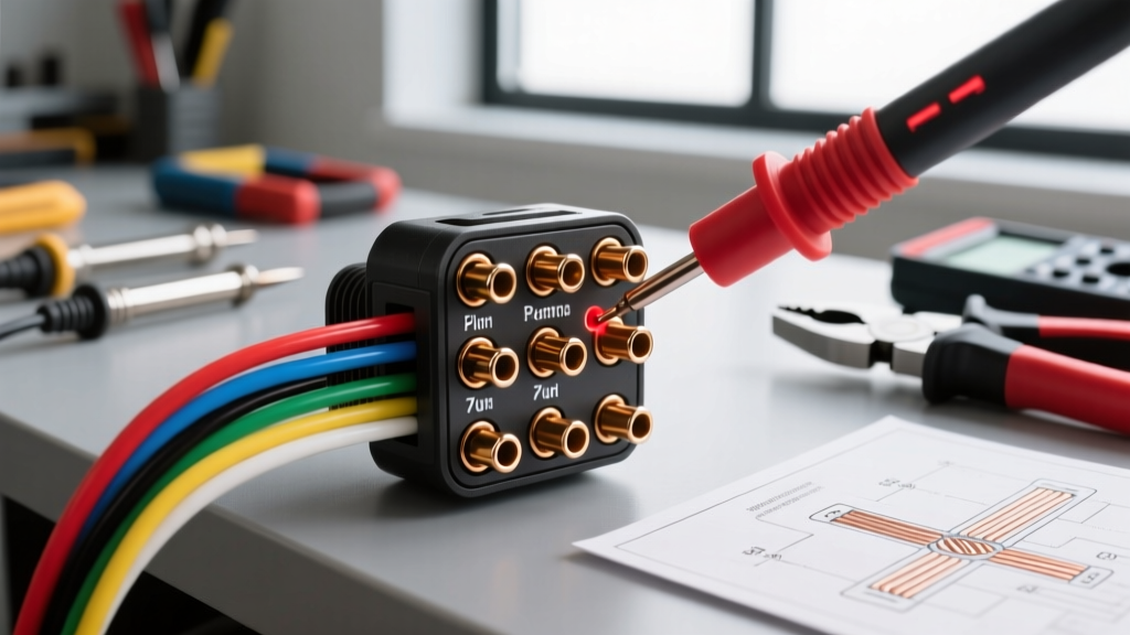
- Circuit Tester Plug: The Pollak PK12-724 or Hopkins 27700 7-way tester plugs directly into the vehicle receptacle, providing instant LED visual confirmation of pin outputs.
- Dielectric Grease: Permatex 22058 or equivalent marine-grade grease to seal connections post-testing.
- Wire Piercing Probes: For testing inline without stripping insulation, minimizing future corrosion points.
Phase 1: Testing the Vehicle-Side Receptacle (Output)
The first step in any diagnostic flow is isolating the fault to either the tow vehicle or the trailer. We begin by verifying the vehicle's output under load.
- Establish a Known Ground: Set your DMM to DC Voltage. Place the black (common) probe on a clean, unpainted metal surface on the vehicle chassis or directly into the Pin 1 (White) ground terminal of the receptacle.
- Verify Auxiliary Power: Insert the red probe into Pin 7 (Black/Red). You should read between 12.4V and 14.2V (depending on alternator output). If you read 0V, check the vehicle's under-hood fuse panel for the 'Trailer Aux' or 'B+ Feed' fuse, commonly a 30A or 40A maxi-fuse.
- Test Lighting Circuits: Turn on the vehicle's parking lights. Probe Pin 2 (Brown). Expect ~12V. Activate the left turn signal; probe Pin 3 (Yellow). The voltage should pulse between 0V and 12V. Repeat for Pin 5 (Green) with the right turn signal.
- Validate the Brake Controller Output: This is where many DIYers fail. Have an assistant press the vehicle's brake pedal while you probe Pin 6 (Blue). You should see a voltage spike. For a more accurate test, use the manual override lever on your brake controller (e.g., Tekonsha Prodigy P3) and measure the voltage. It should smoothly ramp up to 12V at maximum gain.
Phase 2: Testing the Trailer-Side Plug (Continuity)
If the vehicle receptacle tests perfectly, the fault lies in the trailer wiring or the plug itself. According to Fluke's continuity testing guidelines, you must isolate the circuit and ensure zero power is applied before testing resistance.
- Disconnect and Isolate: Unplug the trailer from the vehicle. Ensure all trailer lights are switched off at the source.
- Set DMM to Ohms (Ω): Select the continuity setting (the diode/sound wave symbol) on your multimeter.
- Verify the Ground Path: Place one probe on Pin 1 (White) of the trailer plug and the other on the trailer's bare metal frame. The resistance should be less than 0.5 ohms. If it reads 'OL' (Open Loop), your trailer frame ground is compromised by rust or a broken white wire.
- Test Individual Runs: Place one probe on Pin 2 (Brown) and the other on the positive terminal of a running light fixture (with the bulb removed). You should hear a continuity beep. Repeat for all lighting and brake circuits.
Expert Insight: The Ground Loop Trap
Never rely on the trailer hitch ball and coupler as your primary electrical ground. The white wire (Pin 1) must carry the return current for all trailer circuits. If the white wire is undersized or corroded, current will attempt to return through the hitch, causing erratic brake controller behavior, flickering lights, and accelerated corrosion on the hitch components. Always run a dedicated 10 AWG or 8 AWG white wire directly from the plug to the trailer frame.
Troubleshooting Matrix: Symptoms vs. Root Causes
Use this diagnostic matrix to quickly identify the root cause of common 7-pin trailer wiring failures based on your multimeter readings and visual symptoms.
| Observed Symptom | Probable Root Cause | Multimeter Verification |
|---|---|---|
| Brake controller displays 'S.H.' (Short) error | Blue wire (Pin 6) chafed against frame or corroded plug | Continuity test between Pin 6 and Ground reads near 0Ω |
| LED tail lights hyper-flash or stay dimly lit | Phantom voltage / Lack of load resistance on LED circuits | Voltage reads 2V-4V on Pin 2 when lights are OFF |
| Right turn signal activates tail lights | Ground fault at right-side tail light assembly causing backfeed | Voltage present on Pin 2 when only Pin 5 is energized |
| Trailer battery drains while connected to tow vehicle | Missing isolation relay on Pin 7 (Aux 12V) circuit | Voltage present on Pin 7 when vehicle ignition is OFF |
Advanced Diagnostics: Voltage Drop on Electric Brakes
In 2026, with the widespread adoption of advanced proportional brake controllers and heavier RVs, voltage drop on the electric brake circuit (Pin 6, Blue wire) is a leading cause of braking failure. The brake controller measures the resistance of the circuit to determine if the magnets are functioning. Excessive resistance tricks the controller into throwing an 'O.L.' (Overload) or 'S.H.' (Short) code.
The Math: 10 AWG copper wire has a resistance of approximately 1.018 ohms per 1,000 feet. For a 25-foot run from the front of the trailer to the axles (50 feet round trip), the resistance is roughly 0.05 ohms. At a 10-amp draw (typical for a dual-axle trailer), Ohm's Law (V = IR) dictates a voltage drop of 0.5V. This is acceptable. However, if a previous owner spliced in 14 AWG wire for a repair, the resistance triples, the voltage drop spikes, and the brake magnets receive insufficient current, resulting in dangerous stopping distances.
Component Replacement and 2026 Pricing Guide
When inspection reveals melted pins, severe internal corrosion, or broken strain reliefs, replacement is the only safe option. Do not attempt to salvage a compromised 7-way plug. Here are the top-tier replacements and their current market pricing:
- Pollak 54-761 (Heavy-Duty Die-Cast): Priced around $38 - $45. Features a solid metal housing and screw terminals. Ideal for commercial and heavy agricultural use where impact resistance is critical.
- Hopkins 27700 (Nite-Glow LED Tester/Plug): Priced around $22 - $28. Excellent for DIYers as it includes built-in LED diagnostics on the plug housing itself, allowing you to verify pin outputs without a multimeter once installed.
- Bargman 54-77-003 (Molded 8ft Harness): Priced around $35 - $42. Comes with a pre-molded plug and 8 feet of sealed, jacketed 10/12 AWG wire. This eliminates the need to strip and crimp wires inside the plug housing, drastically reducing future moisture ingress.
For comprehensive wiring schematics and vehicle-specific tow package installation guides, etrailer's wiring FAQ remains one of the most robust databases for matching OEM factory tow ports to aftermarket 7-pin adapters.
Final Inspection Protocol
After completing repairs or replacements, perform a final 'shake test.' While an assistant monitors the trailer lights and brake controller, vigorously shake the 7-pin plug at the receptacle interface. Any flickering indicates loose internal terminals or a worn receptacle collar. Apply a liberal coating of marine-grade dielectric grease to the pins before final insertion to displace moisture and ensure a reliable connection for the road ahead.